


J-200
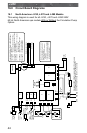
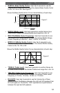
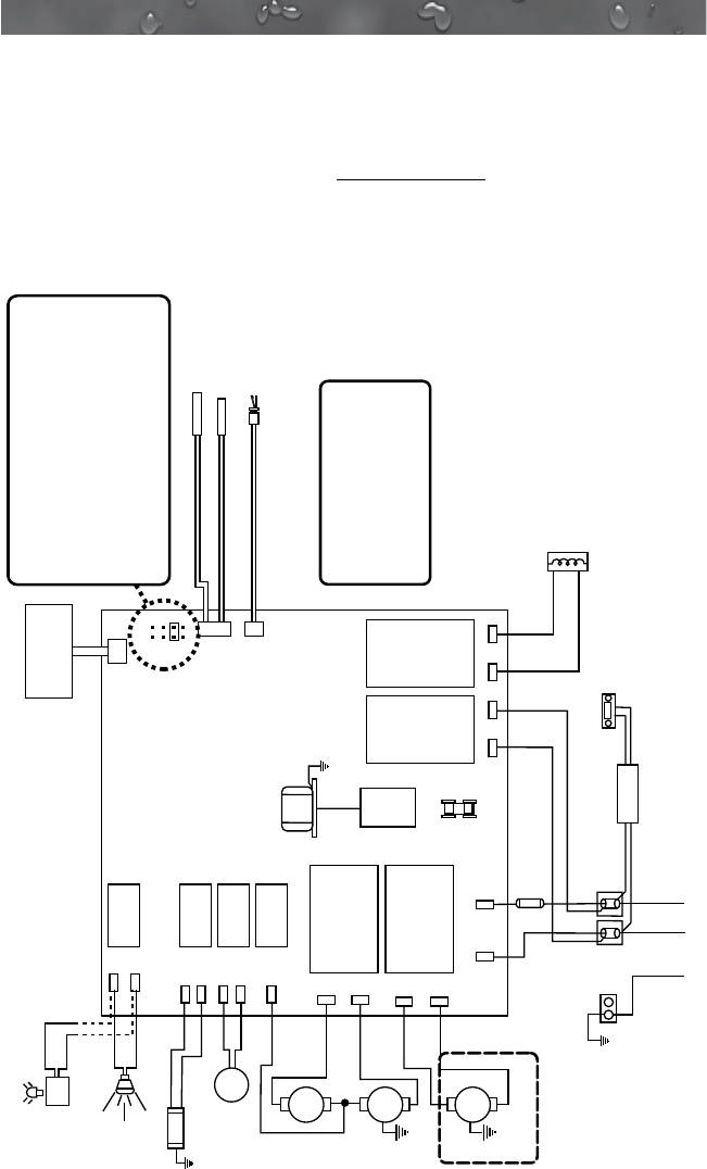
16.0 Circuit Board Diagrams
This wiring diagram is used for all J-230, J-270 and J-280 240V
60 Hz North American spa models With or Without the Circulation Pump
Option.
Optional
Stereo
Power Supply
OZONATOR (OPTIONAL)
O
3
GRN
TB1
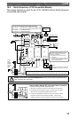
Standard 240 VAC, 3-Wire Connection (60Hz, 1-Phase Service)
USE COPPER CONDUCTORS ONLY. WIRE SIZE MUST
BE APPROPRIATE PER NEC AND/OR LOCAL CODES
RED
RED
J6
BLK
J5
WHT
WHT
WHT
RED
BLK
BLK
BLK
WHT
BLK
RED RED
BLK BLK
BLK
2
1
FLOW SWITCH
HI - LIMIT / FREEZE SENSOR
TEMPERATURE SENSOR
J1
J2
J3
F1
30A, 250V
SC-30
PUMP 1
PUMP 2
TRANSFORMER
240 VAC
J4
F1
JP1
4
2
3
1
6 5
8 7
7 6 2 4
HI
HI
LO
C
Control Panel
CIRC.
PUMP
J20
K1
K2
K3
K4
K5
K6 K7 K8
J21
J11
J12
J13
J14
J15
J16
J17
J18
J19
J7 J8
J9
J10
This device complies with Part 15 of the
FCC rules. Operation is subject to the
following two conditions:
1. This device may not cause harmful
interference.
2. This device must accept any inteference
received including interference that may
cause undesired operation.
Heater
5.5 kW
240 VAC
WHT
BLK
WHT
BLK
Standard
Footwell
Light
* Shown
with Optional
Circulation
Pump
Optional
LED Lighting
System DCU
OR
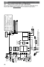
Logic Jumper Settings (Factory Defaults Shown)
JP1 1-2 ON = 40A Logic
JP1 1-2 OFF = 50A Logic (Factory Default Setting)
JP1 3-4 ON = 2 Pump Operation (Not used on J-230)
JP1 3-4 OFF = 1 Pump Operation
JP1 5-6 ON = 60A Logic (Remove JP1 1-2 Jumper)
(Not used on J-230)
JP1 5-6 OFF = Leave off for 40A or 50A Logic
JP1 7-8 ON = °C Temperature Display
JP1 7-8 OFF = °F Temperature Display
Not used on J-230
44