


SECTION 2—PARTS AND INSTALLATION
Part No 1150695 15 Recessed Side Entry Bath Tubs
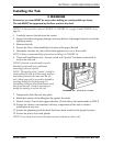
Installing the Tub
ƽ WARNING
Protective eye wear MUST be worn when drilling to avoid possible eye injury.
The tub MUST be supported by the floor and not the deck.
NOTE:Forthisprocedure,refertoFIGURE 2.2,FIGURE 2.3onpage16andFIGURE 2.4on
page16.
1. Carefullyremovethetubfromthecarton.
2. Inspectthetubforshippingdamageorfactorydefects.Ifdamageisfound,contactthe
shippingcarrier.
3. Measurethetub.
4. Ensuretheflooroftheinstallationlocationwillsupportthetub.
5. Determinewhethertheunitwillbebuiltagainstone,twoorthreewalls.
NOTE:FollowrecommendedfloorplanwheninstallingtubFIGURE 2.4.
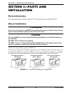
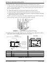
6. Threewallinstallationonly‐Ensureastudwall“pocket”hasbeenconstructedto
receivethetubunit.
NOTE:Ifdesired,awoodennailermaybe
attachedtostudwallsasanadditional
mountingfixtureforthetub.
NOTE:Theopeningofthe“pocket”shouldbe
sizedtoallowtheunittoslideineasily,without
anybindingbetweenthestudsandthetub
unit.Minorgapswillbecoveredbydrywallor
panelingduringthefinishingstage.In
remodelingsituationswheretub/showerunits
havebeenremoved,itmaybenecessaryto
modifytheopeningtoreceivethetub.
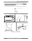
FIGURE 2.2 Stud Wall “Pocket”
7. Temporarilyslidetheunitintoplace.
8. Markthelocationofthefiberglasslipagainstthestuds.
9. Mount2‐inchx2‐inchcleatsapproximately1/8‐inchbelowthemarksmadein
STEP 8.
10. Ensurethecleatstonotinterferewithanycomponentsoftheunitorrestrict
installationinanyway.
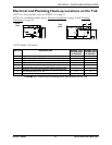
11. Ensuretheplumbingandelectricallineshavebeenroutedtotheproperlocation.
12. Ensuretheunitislevelandplumb.
NOTE:Usea4‐footleveltolevelthetubfromfronttobackandsidetoside.