


MHD56391 - Edition 2 9
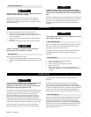
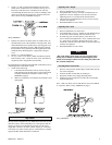
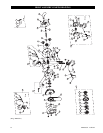
3. Using a “C” link, join the old load chain to the new load
chain. (If the old load chain was installed correctly, the “C”
link assures end link of new load chain will be correctly
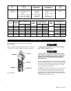
reeved through the hoist.) Be sure welds of “standing” links
on the new load chain are facing away from the hoist load
sheave. Refer to Dwg. MHP0042
on page 9.
(Dwg. MHP0042)
4. Run the new chain to its anchor point. On smaller units, use
the hand chain to move the load chain. On larger units, load
chain installation can be speeded up by removing gear cover,
support plate and taking out gears. With the gears removed,
the load chain can be pulled by hand through the hoist body
and hook blocks. Reinstall gears, support plate, and gear
cover.
5. Remove “C” link and old chain.
6. On 1/2, 1 and 1-1/2 ton hoists, anchor load chain to bottom
hook assembly. On 2, 3 and 5 ton units, secure load chain to
suspension plates using anchor bolt assembly.
For information on connecting unloaded end of load chain, refer to
‘Attaching End of Load Chain’ section.
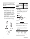
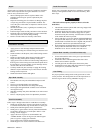
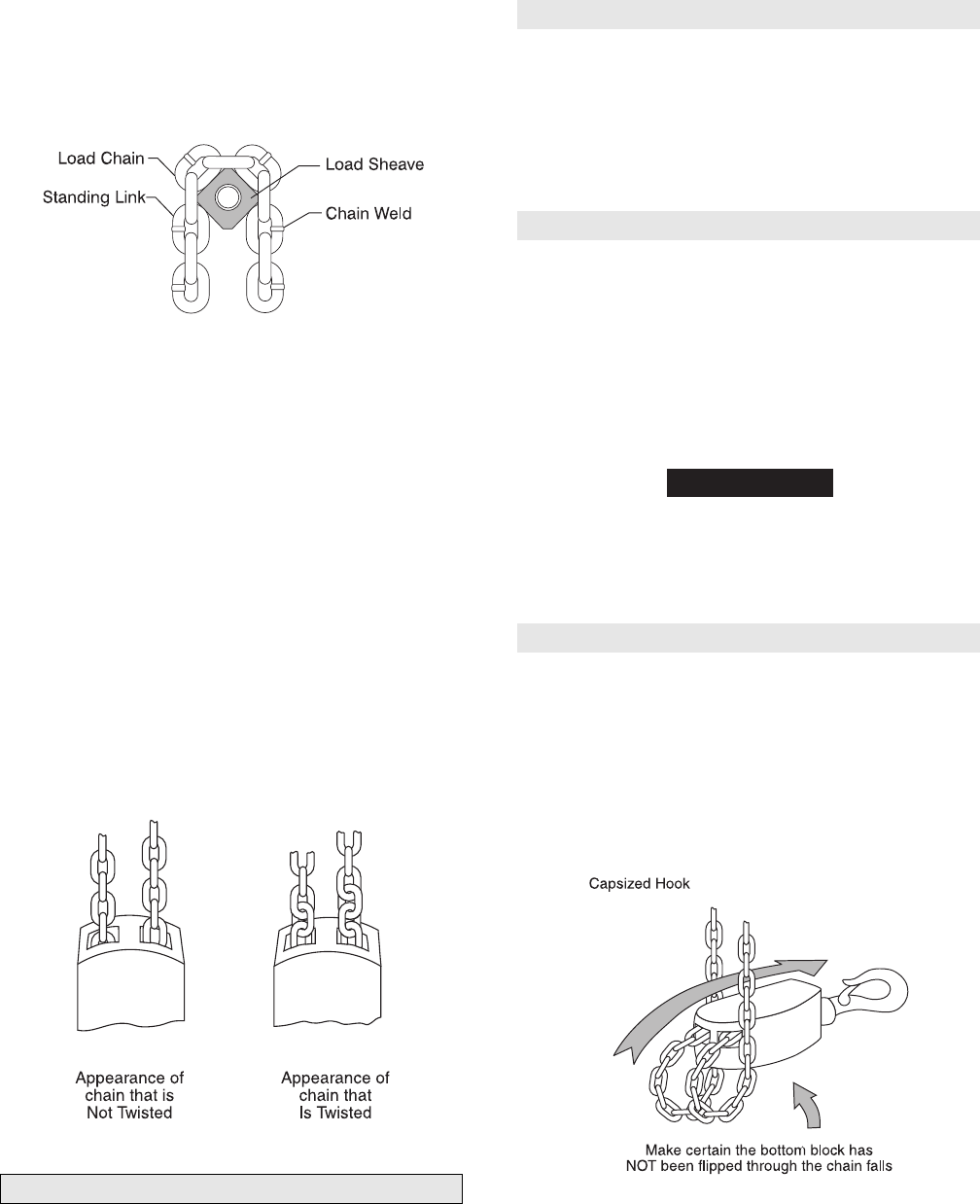
7. Check for the following:
a. Load chain did not become twisted, when reeving the
load chain between the idler sheave on the bottom hook
assembly and the hoist load sheave. Refer to Dwg.
MHP0020
on page 9.
b. Make sure load chain is reeved between load sheave and
chain guides.
(Dwg. MHP0020)
Slip Clutch
The slip clutch is designed to slip, (handwheel rotates but no load
chain movement), when attempting to lift a load greater than the
capacity of the hoist. To adjust the slip clutch you will need a
weight that is known to be 150% of hoist capacity or a scale that
will read at least 150% of hoist capacity. Attach hoist to a suitable
support and then attach load/scale to load hook.
Adjusting with a Weight
1. Remove handwheel cover from hoist.
2. Using hand chain ‘hoist up’ the load. If load does not rise
tighten nut 1/4 turn. Attempt to raise the load. Continue
tightening nut in 1/4 turn increments until load raises.
3. Then lower the load and back the nut off 1/4 turn. The slip
clutch is now adjusted.
4. Reinstall handwheel cover to hoist.
Adjusting with a Scale
1. Remove handwheel cover from hoist.
2. Using hand chain, ‘hoist up’. Needle on scale should only go
up to 150% of hoist capacity, then the clutch will slip.
3. If clutch slips prior to 150% capacity, ‘hoist down’ (to
remove tension) and tighten nut 1/4 turn. Continue this ‘hoist
up’, ‘hoist down’ procedure, adjusting the nut in 1/4 turn
increments, until the scale reads 150% of rated load. The slip
clutch is now adjusted.
4. Reinstall handwheel cover to hoist.
NOTICE
• Due to the nature of the design, an exact precision clutch
setting may be difficult to obtain. Repeated slipping of the
clutch, in an attempt to obtain an exact setting may reduce the
life of clutch components.
Attaching End of Load Chain
1. Remove cotter pin from anchor hanger. Push anchor pin into
one of the side plates.
2. Position end link of load chain on anchor pin.
3. Reposition anchor pin to engage both side plates.
4. Install cotter pin in anchor pin on either side of load chain
and bend ends apart.
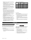
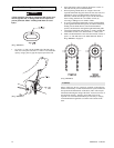
On 2, 3 and 5 ton hoists, ensure load chain is not twisted, kinked
or “capsized”. Refer to Dwg. MHP0043 on page 9.
(Dwg. MHP0043)