


MHD56391 - Edition 2 11
Repair
Actual repairs are limited to the removal of small burrs and other
minor surface imperfections from gears and shafts. Use a fine
stone or emery cloth for this work.
1. Worn or damaged parts must be replaced. Refer to the
applicable parts listing for specific replacement parts
information.
2. Inspect all remaining parts for evidence of damage. Replace
or repair any part which is in questionable condition. The
cost of the part is often minor in comparison with the cost of
redoing the job.
3. Smooth out all nicks, burrs, or galled spots on shafts, bores,
pins, and bushings.
4. Examine all gear teeth carefully, and remove nicks and burrs.
5. Polish the edges of all shaft shoulders to remove small nicks
which may have been caused during handling.
6. Remove all nicks and burrs caused by lockwashers.
Assembly
Load Sheave Assembly
1. Apply grease to roller bearings and position them in the
groove of the bearing race located on the gear end of the load
sheave.
2. Install load sheave in side plate, ensure roller bearings remain
in position.
3. Install two-chain guides, chain stripper assembly, anchor
hanger assembly, and top hook assembly in side plate.
4. Apply grease to the second set of roller bearings and position
them in groove of the bearing race located on the plain end of
the load sheave. The same number of roller bearings must be
used on either side of the load sheave.
5. Carefully install side plate assembly to engage the locating
diameters of parts installed in steps 3 and 4. Ensure all roller
bearings remain in position.
6. Install lockwashers and nuts and tighten.
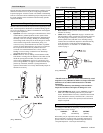
Slip Clutch Assembly
1. Place double cone onto pins in handwheel and press until
seated.
2. Insert screws through double cone and tighten.
3. Insert single cone into double cone along with spring.
4. Insert support through backside of double cone. Thread nut
onto support loosely.
5. Slide this assembly onto pinion shaft and secure with nut and
cotter pin.
6. Refer to ‘Adjusting Slip Clutch’ for adjustment procedures.
Gear End Assembly
Follow steps 1 through 6 described in ‘Load Sheave Assembly’.
1. Install gear on load sheave. Ensure recessed side of gear face
is outward. Install retainer ring on load sheave to secure gear.
2. Install pinion shaft through the center of load sheave.
3. Install gears so gear teeth are correctly timed and end shafts
are located in bearing sleeves in side plate. Refer to ‘Gear
Timing’ section on page 11.
4. Apply a thick coat of grease as recommended in the
“LUBRICATION” section to all gear teeth. Install support
plate over gears to engage gear end shafts.
5. Secure support plate with nuts and lockwashers.
6. Install the gear cover. Secure with three nuts and screws.
Brake End Assembly
Follow steps 1 through 6 described in ‘Load Sheave Assembly’
and steps 1 through 6 described in ‘Gear End Assembly’, then
below steps.
CAUTION
• The brake will not operate properly if there is oil on the
brake discs.
1. Thread brake hub onto pinion shaft until snug. Stepped side
of brake hub must face out.
2. Install first brake disc followed by ratchet disc and second
brake disc. Ratchet disc teeth must engage the two pawls
mounted on side plate assembly. Counterclockwise rotation
of the ratchet disc must be possible.
3. Secure load sheave to prevent rotation and thread handwheel
onto pinion shaft and secure with nut. Tighten nut until snug
and then back nut off until first slot is aligned with pin hole in
pinion shaft. Install cotter pin and bend ends apart.
4. Wrap hand chain around handwheel and feed ends through
slots provided in hand chain wheel cover. Install the
handwheel cover. Secure with three nuts and screws.
Bottom Hook Assembly (2, 3 and 5 ton hoists only)
1. Grease and install the rollers in the groove provided in the
bore of the idler sheave.
2. Install idler sheave shaft through the idler sheave bore.
Ensure rollers remain in position.
3. Carefully place the assembled parts between the plates.
4. Install hook between plates and clamp plate halves together
with capscrews, lockwashers and nuts.
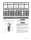
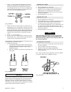
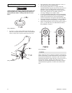
Gear Timing
For proper operation, timing marks on the gears must be in the
correct positions. The timing marks are circular impressions on
the faces of gears. Refer to Dwg. MHP0833
on page 11.
(Dwg. MHP0833)