


10 MHD56391 - Edition 2
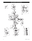
General Disassembly
The following instructions provide the necessary information to
disassemble, inspect, repair, and assemble the hoist. Parts
drawings of the hoist assembly are provided in the parts section. If
a hoist is being completely disassembled for any reason, follow
the order of the topics as they are presented. It is recommended
that all maintenance work on the hoist be performed on a bench.
In the process of disassembling the hoist, observe the following:
1. Never disassemble the hoist any further than is necessary to
accomplish the needed repair. A good part can be damaged
during the course of disassembly.
2. Never use excessive force when removing parts. Tapping
gently around the perimeter of a cover or housing with a soft
hammer, for example, is sufficient to break the seal.
3. Do not heat a part with a flame to free it for removal, unless
the part being heated is already worn or damaged beyond
repair and no additional damage will occur to other parts. In
general, the hoist is designed to permit easy disassembly and
assembly. The use of heat or excessive force should not be
required.
4. Keep the work area as clean as practical, to prevent dirt and
other foreign matter from getting into bearings or other
moving parts.
5. When grasping a part in a vise, always use leather-covered or
copper-covered vise jaws to protect the surface of the part
and help prevent distortion. This is particularly true of
threaded members, machined surfaces and housings.
6. Do not remove any part which is press fit in or on a
subassembly unless the removal of that part is necessary for
repairs or replacement.
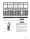
Disassembly
Accessing Gear End
1. Remove the three nuts from gear cover.
2. Remove gear cover.
3. Remove nuts along with lockwashers from support plate .
4. Remove support plate, gears and bearings.
5. Remove retainer ring from load sheave and pry off gear.
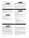
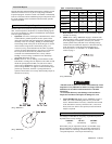
Accessing Brake End
1. Remove the three nuts and screws from handwheel cover.
2. Remove handwheel cover.
3. Remove cotter pin and nut from pinion shaft.
4. Secure load sheave to prevent rotation and unscrew
handwheel from pinion shaft. Handwheel is left hand
(counterclockwise) threaded.
5. Remove brake discs and ratchet disc.
6. Secure load sheave to prevent rotation and unscrew brake
hub from pinion shaft.
NOTICE
• If ratchet pawls or springs are damaged or not functioning
then remove retainer ring and replace damaged parts.
Slip Clutch Disassembly
1. Remove cotter pin and nut.
2. Pull handwheel/slip clutch assembly off of pinion shaft.
3. Remove nut from support and separate support, spring and
single cone.
4. Remove screws and carefully pry double cone off of
handwheel.
Accessing Load Sheave
Follow steps 1 through 5 in ‘Accessing Gear End’ and steps 1
through 6 in ‘Accessing Brake End’, then steps below.
1. Remove nuts and lockwashers from side plate.
2. Pull side plate away from studs in side plate.
3. Remove the top hook assembly, roller bearings, two-chain
guides, chain stripper, and anchor hanger.
4. Lift load sheave from side plate. Being careful to catch roller
bearings as they become free.
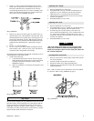
Bottom Hook Disassembly (2, 3 and 5 ton)
1. Remove three capscrews, lockwashers and nuts.
2. Separate plates and remove hook.
3. Lift out sheave assembly. Carefully slide idler sheave shaft
from idler sheave and remove rollers.
Cleaning, Inspection and Repair
Use the following procedures to clean and inspect the components
of the hoist.
Cleaning
Clean all hoist component parts in an acid free solvent (except for
the brake disc). The use of a stiff bristle brush will facilitate the
removal of accumulated dirt and sediments on the gears and
frames. Dry each part using low pressure, filtered compressed air.
Inspection
All disassembled parts should be inspected to determine their
fitness for continued use. Pay particular attention to the following:
1. Inspect all gears for worn, cracked, or broken teeth.
2. Inspect shafts for ridges caused by wear. If ridges caused by
wear are apparent on shafts, replace the shaft.
3. Inspect all threaded items and replace those having damaged
threads.
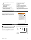
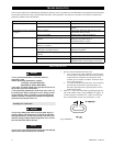
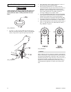
4. Measure the thickness of the brake discs. If brake discs do
not have uniform thickness or are less than the discard
dimension shown in Table 3: Brake Disc Chart, replace brake
discs.
Table 3: Brake Disc Chart
1/2 - 5 ton
in
mm
Normal 0.10
2.5
Discard 0.075
1.875
5. Inspect ratchet pawls and springs on side plate assembly.
Replace parts if pawls and or springs are damaged or fail to
operate.