


MHD56109 - Edition 9 9
MAINTENANCE
WARNING
• Never perform maintenance on hoist while it is supporting a
load.
• Before performing maintenance, tag hoist:
WARNING - DO NOT OPERATE -
EQUIPMENT BEING REPAIRED.
• Only allow personnel trained in the operation and service of
this product to perform maintenance.
• After performing any maintenance on hoist, test to 125% of
its rated capacity before returning to service. Testing to 150%
of rated capacity might be required to comply with standards
and regulations set forth in areas outside of the USA.
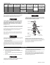
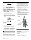
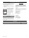
Installing New Load Chain
Refer to Dwg. MHP0042 on page 9.
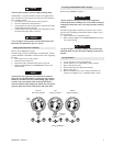
1. Ensure welds of “standing” links on new load chain are
facing away from load sheave assembly (7).
2. Ensure load chain (55) is reeved between load sheave
assembly (7) and chain guides (6) and (8).
3. Bottom hook assembly (50) must be on left fall of load chain
(55) and right fall must have a chain stopper (54) attached to
end link.
(Dwg. MHP0042)
NOTICE
• Right and left designations are as viewed from hand lever
side of hoist.
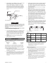
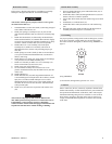
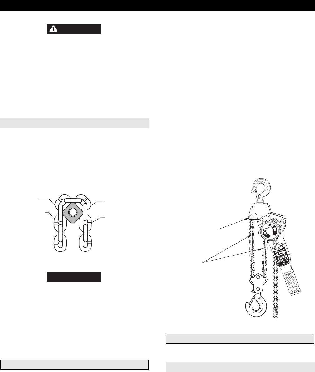
4. On 6 ton hoists feed load chain through bottom block
assembly and secure to top hook bracket with capscrew (49)
and nut (60). Ensure load chain is straight and not twisted.
Chain weld on standing links will be to the inside of bottom
hook idler sheave (56). Refer to Dwg. MHP0834 on page 9.
5. Lubricate new load chain before using hoist. Refer to
“LUBRICATION” section for recommended lubricants.
General Disassembly
The following instructions provide necessary information to
disassemble, inspect, repair and assemble hoist. Hoist assembly
parts drawings are provided in “PARTS” section.
If a hoist is being completely disassembled for any reason, follow
the order of the topics as they are presented. It is recommended
that all maintenance work on hoist be performed on a bench in a
clean dust free area.
In the process of disassembling the hoist, observe the following:
1. Never disassemble hoist any further than is necessary to
accomplish needed repair. A good part can be damaged
during the course of disassembly.
2. Never use excessive force when removing parts. Tapping
gently around the perimeter of a cover or housing with a soft
hammer, for example, is sufficient to break the seal.
3. Do not apply heat to a part to free it for removal, unless part
being heated is already worn or damaged beyond repair and
no additional damage will occur to other parts.
In general, hoist is designed to permit easy disassembly and
assembly. Use of heat or excessive force should not be
required.
4. Keep work area as clean as practical, to prevent dirt and
other foreign matter from getting into bearings or other
moving parts.
5. When grasping a part in a vise, always use leather-covered
or copper-covered vise jaws to protect the surface of the part
and help prevent distortion. This is particularly true of
threaded members, machined surfaces and housings.
6. Do not remove any part which is press fit in or on a
subassembly unless removal of that part is necessary for
repairs or replacement.
(Dwg. MHP0834)
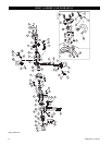
Hoist Disassembly
Refer to Dwg. MHP0773 on page 12.
Accessing Brake End
1. Remove retainer wire (30) and lift off cover (29).
2. Remove split pin (71) and castle nut (70) from
drive shaft (3).
3. Remove screw (69) and washer (68).
4. Remove two screw (64) and washer (65) from lever handle
assembly (25). Lift off lever handle assembly (25).
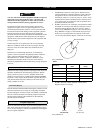
Load Sheave
Chain Weld
Standing Link
Load Chain
Weld on standing links
must be to outside of
top load sheave and
to inside of bottom
hook idle sheave
Attach chain
end to hoist top
hook bracket
6 ton Hoist
F
R
E
E
L
O
A
D