


MHD56109 - Edition 9 11
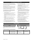
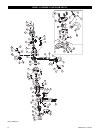
Brake End Assembly
Follow steps 1 through 6 described in ‘Load Sheave Assembly’
and steps 1 through 5 described in ‘Gear End Assembly’.
CAUTION
• The brake will not operate properly if there is oil or grease
on brake friction disk (17).
1. Thread disk hub (15) onto drive shaft (3) until snug. Stepped
side of brake hub must face out.
2. Install pawl springs (13) and pawls (14) to posts on side
plate assembly B (brake end) (12) and secure with snap rings
(63).
3. Install first friction disk (17) followed by ratchet disk (18)
and second friction disk (17). Ratchet disk teeth must engage
two pawls (14) mounted on side plate assembly B (12). Only
clockwise rotation of ratchet disk (18) must be possible.
4. Install brake lever cover assembly (19) on side plate
assembly B (12). Brake cover assembly will locate on
threaded spacers (94). Secure with prevailing torque type
nuts (60).
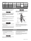
5. Install spring (16) on drive shaft (3) then secure load sheave
(7) to prevent rotation and thread disk hub (15) onto drive
shaft (3) until snug.
6. Install change over spring (24), spring shaft (23) and change
over pawl (22) in lever handle assembly (25).
7. Install lever assembly on brake lever cover assembly (19).
Secure with washers (65) and screw (64).
8. Install screws (64) and washers (65).
9. To assist further assembly move selector lever to UP
position. Install hand wheel (28) and install screws (69) and
washer (68).
10. Install bushing (31).
11. Install and castle nut (70) until snug and then back nut off
3/4 turn and align slot with pin hole in drive shaft (3). Install
split pin (71) but do not bend ends apart. Test to ensure
adjustment block will freely move to free chain position. If
not, back off nut one more slot and retest. Install and bend
cotter pin ends apart.
12. Install cover (29) and secure in position with retainer wire
(30).
NOTICE
• Ensure hoist will properly shift from UP, DOWN and
NEUTRAL positions using selector lever. With selector lever
in NEUTRAL (center) position, turn free chain knob
counterclockwise. Ensure brake disengages and load chain can
be pulled in both directions without sticking or binding.
Bottom Hook Assembly
1. On 6 ton double fall hoists grease and install rollers (97) in
bore of idler sheave (56).
2. Install idler sheave shaft (96) through idler sheave (56) bore.
Ensure rollers (97) remain in position.
3. Secure idler sheave shaft (96) with retainer rings (95) at both
ends.
4. Install hook (51) in hook block (57).
5. Install idler sheave shaft (96) and secure with retainer ring
(95).
6. On single fall hoists install last link of load chain in hook
assembly and install capscrew (52) and nut (77).
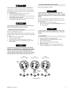
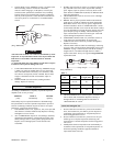
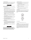
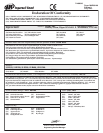
Gear Timing
For proper operation, timing marks on driver shaft gears (2) must
be in correct positions. Timing marks are circular impressions
near center of driver shaft gears (2). Refer to Dwg. MHP0827 on
page 11.
(Dwg. MHP0827)
(3/4 ton shown) timing marks typical for 3/4 - 6 ton
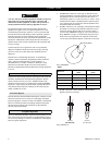
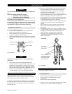
Load Test
Prior to initial use, all new, extensively repaired or altered hoists
shall be load tested by or under the direction of a person trained in
the operation and maintenance of this hoist, and a written report
furnished confirming rating of hoist. Test hoist to 125% of rated
hoist capacity. Testing to more than 125% may be necessary to
comply with standards and regulations set forth in areas outside
of the USA.
3/4 ton