


10 MHD56109 - Edition 9
5. Remove change over pawl (22), spring shaft (23) and change
over spring (24) from lever handle assembly (25).
6. Carefully pry change hand wheel (28) from change
over gear (20).
7. Remove screw (64), washers (65) and prevailing torque type
nut (60) from threaded spacers (94). Remove brake cover
assembly (19).
8. Secure drive shaft (3) to prevent rotation and unscrew disk
hub (15).
9. Remove friction disk (17), ratchet disk (18) and free spring
(16).
10. Remove snap ring (63) from posts on side plate assembly B
(12). Remove pawls (14) and pawl spring (13).
Accessing Gear End
1. Remove four prevailing torque type nuts (60) from side plate
threaded spacers (94).
2. Remove gear case assembly (1).
3. Remove driver shaft assembly (2).
4. Remove snap ring (62) from load sheave assembly (7) if
complete hoist is to be disassembled.
Accessing Load Sheave
Follow steps 1 through 10 in ‘Accessing Brake End’ and steps 1
through 4 in ‘Accessing Gear End’.
1. Slide out Drive shaft (3) from gear end.
2. Carefully remove side plate assembly B (brake side) (12).
3. Remove chain leaders (9) and (11), stripper (10),
guide ring B (8) and top hook (45) with top pin (48).
4. Remove splined gear (4) from load sheave assembly (7).
Remove load sheave from side plate assembly A (gear side)
(5).
5. Only if necessary, tap side plate threaded spacers (94) from
side plate assembly A (gear side) (5).
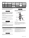
Bottom Hook Disassembly
1. On single fall hoists remove prevailing torque type nut (77)
and capscrew (52). Separate load chain from hook.
2. On 6 ton double fall hoists remove retainer rings (95).
3. Carefully slide idler sheave shaft (96) from hook block (57).
Remove idler sheave (56) and remove rollers (97) from idler
sheave (56).
4. Slide out idler sheave shaft (96) and remove bottom hook
(51).
Cleaning, Inspection and Repair
Use the following procedures to clean and inspect the components
of hoist.
Cleaning
Clean all hoist component parts in solvent (except for brake
disks). Use of a stiff bristle brush will facilitate removal of
accumulated dirt and sediments on gears, shafts and housings.
Dry each part using low pressure, filtered compressed air. If brake
disks are oil-soaked, they must be replaced.
Inspection
All disassembled parts should be inspected to determine their
fitness for continued use. Pay particular attention to the
following:
1. Inspect all gears for worn, cracked, or broken teeth.
2. Inspect shafts for ridges caused by wear. If ridges caused by
wear are apparent on shafts, replace shaft.
3. Inspect all threaded items and replace those having damaged
threads.
4. Inspect brake disks for oil. If brake disks are oil-soaked,
replace brake disks.
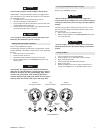
5. Measure thickness of brake disks. New brake disk thickness
is 3 mm. Discard brake disks if thickness is 2 mm or less.
Repair
Actual repairs are limited to removal of small burrs and other
minor surface imperfections. Use a fine stone or emery cloth for
this work.
1. Worn or damaged parts must be replaced. Refer to applicable
parts listing for specific replacement parts information.
2. Inspect all remaining parts for evidence of damage. Replace
or repair any part which is in questionable condition. The
cost of the part is often minor in comparison with the cost of
redoing the job.
3. Smooth out all minor nicks, burrs, or galled spots on shafts,
bores, pins or spacers.
4. Polish edges of all shaft shoulders to remove small nicks
which may have been caused during handling.
5. Remove all nicks and burrs caused by lockwashers.
Hoist Assembly
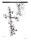
Refer to Dwg. MHP0773 on page 12.
Load Sheave Assembly
1. Install side plate threaded spacers (94) in side plate assembly
A (gear side) (5).
2. Install load sheave (7) in side plate assembly A (5).
3. Apply grease to Bearing A (91) located on end of load
sheave (7).
4. Install chain leaders (9) and (11), stripper (10), guide ring B
(8) and top hook (45) on top pin (48) in side plate assembly
A (5).
5. Carefully install side plate assembly B (brake end) (12) to
engage locating diameters of parts installed in step 4.
6. Push side plates together to ensure all parts are located and
secure.
Gear End Assembly
Follow steps 1 through 6 described in ‘Load Sheave Assembly’.
1. Install splined gear (4) on load sheave (7). Install snap ring
(62) on load sheave (7) to secure splined gear (4).
2. Install drive shaft (3) through center of load sheave (7).
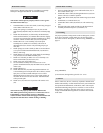
3. Install driver shaft gears (2) so gear teeth are correctly timed
and spigots locate in bearing sleeves in side plate assembly
A (5). Refer to ‘Gear Timing’ section.
4. Apply a thick coat of grease as recommended in
“LUBRICATION” section to all gear teeth. Install gear case
(1) over driver shaft (2) to locate and engage gear spigots.
5. Secure gear cover with prevailing torque type nut (60).