


6
CD-7 thru CD-15 Infinity Corona Discharge Ozone Generator
2. G.F.C.I. has tripped.*
a. Check power cord and reset G.F.C.I.
3. Circuit breaker has tripped.*
a. Reset breaker.
*If G.F.C.I. or breaker continue to trip after reset, call
for technical assistance.
Symptom: “
Ozone power
” indicator light out.
1. If optional ORP is installed, ORP may have shut down
the generator when ORP level reached setpoint.
a. Wait for ORP to come down. Generator will
restart when ORP level is below set point.
2. Abnormal operating condition exists.
a. Check red fault indicator lights. Refer to corre-
sponding symptom and corrective action.
Symptom: “
Vacuum
” indicator light is on indicating out of
range vacuum being supplied.
1. Injector not supplying adequate suction.
a. Check pump and ensure water is flowing through
injector.
b. Check by-pass valve and adjust if necessary to
obtain proper pressure differential in order to
reestablish suction.
2. Injector supplying too much suction.
a. Check by-pass valve and adjust to obtain proper
suction.
b. Check system back pressure and increase to
reduce suction.
3. Another abnormal condition exists causing ozone out-
put solenoid valve to be closed.
a. Check red fault indicator lights. Refer to corre-
sponding symptom and corrective action.
b. Solenoid valve may be stuck in closed position.
Free solenoid plunger and return system to
normal operation.
Symptom: “
High coolant temperature
” indicator light is
on indicating ozone module temperature over 150°F.
1. Coolant water flow has been interupted.
a. Check all tubing connections, ensureing tight,
leak free connections.
b. Trace tubing and look for blockage of flow.
c. Re-establish proper coolant water flow.
Symptom: “
High transformer temperature
” indicator light
is on indicating high voltage transformer temperature over
150°F.
1. Enclosure ventilation is blocked.
a. Check air filter on bottom left-hand side of
enclosure for blockage.
b. Clear blockage or clean filter.
c. Restart system and allow transformer to cool.
When temperature returns to normal system will
return to normal operation.
2. Excessive ambient temperatures in installation area.
a. Generator should not be exposed to ambient
temperatures above 100°F. Higher temperatures
may damage generator components.
Symptom: “
Water backflow detected
” indicator light is on.
1. Water has backed into generator from injector.
a. Establish proper water flow through injector and
correct suction.
b. Drain Back Flow Preventer by first routing drain
tubing out of cabinet.opening cabinet and opening
1/4" stainless steel ball valve.
c. After water has completly drained close drain
valve, secure cabinet door and restart system.
Symptom: CD Module is not operating. Ozone output
has dropped.
1. No power to the generator module from the power supply:
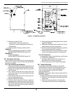
a. Check H.V. cables for breaks or loose connections,
replace if necessary.
b. Check for power at input terminals of the H.V.
transformers.*
c. Check ozone power relay for loose connections
or faulty operation.
*CAUTION: HIGH VOLTAGE.
Symptom: No air flow through the generator. The air flow
meter indicates 0 scfh flow.
1. Flowmeter control valve is improperly set:
a. Open flowmeter valve until proper air flow is
indicated (~8 scfh for CD-7, ~14 scfh for CD-15).
2. Air compressor is not operating properly.
a. Listen for air compressor operation.
b. Check all tubing connections from the air compres-
sor through the system for leaks.
SECTION 5
Replacement Parts and Order Information
5A. Ordering information:
For replacement parts call DEL at 1-800-676-1335.
Be prepared with the following information:
· Customer Name · Customer Address
· DEL Model Number · DEL Serial Number
· Date Purchased · Proof of Purchase
5B. Standard replacement parts list:
1. Compressor rebuild kit, CD-7 .................. 9-1007
2. Compressor rebuild kit, CD-15 ................ 9-1015
3. Ventilation air filter................................... 7-0401
4. High voltage electrode............................. 9-0540
5. Ozone tubing, Teflon ............................... 7-0126
6. Ozone tubing, Stainless Steel ................. 8-0098
7. Ozone module gasket (1 ea.) .................. 7-0801
8. Installation & Operations Manual ............ 4-0401