


2
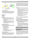
CD-7 thru CD-15 Infinity Corona Discharge Ozone Generator
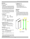
2B. Mounting
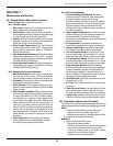
2B-1. Wall Mount Option
1. Attach two mounting brackets to wall using anchors
appropriate for mounting surface.
See figure 1
.
2. Using 1/4"-20 bolts (with washers as shown) se-
cure generator to mounts.
2B-2. Floor Mount Option
1. Use the 4 1/4"-20 bolts with washers to secure feet
to bottom of cabinet.
2. Stand upright and securely fasten to concrete slab
using appropriate anchors and bolts.
2C. Electrical
Main power circuit: Unit is supplied with a standard
power cord. Plug cord into standard 110V grounded,
grounding type receptacle only. NOTE: The circuit must
be protected by a ground-fault circuit interrupter (GFCI)
installed in accordance with electrical codes.
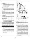
2D. Plumbing
Ozone gas is introduced to the pool circulation line using
a venturi injector. Suction developed by the venturi allows
the CD to operate safely under vacuum.
See installation
manual for MX-600-CD for proper venturi installation
.
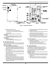
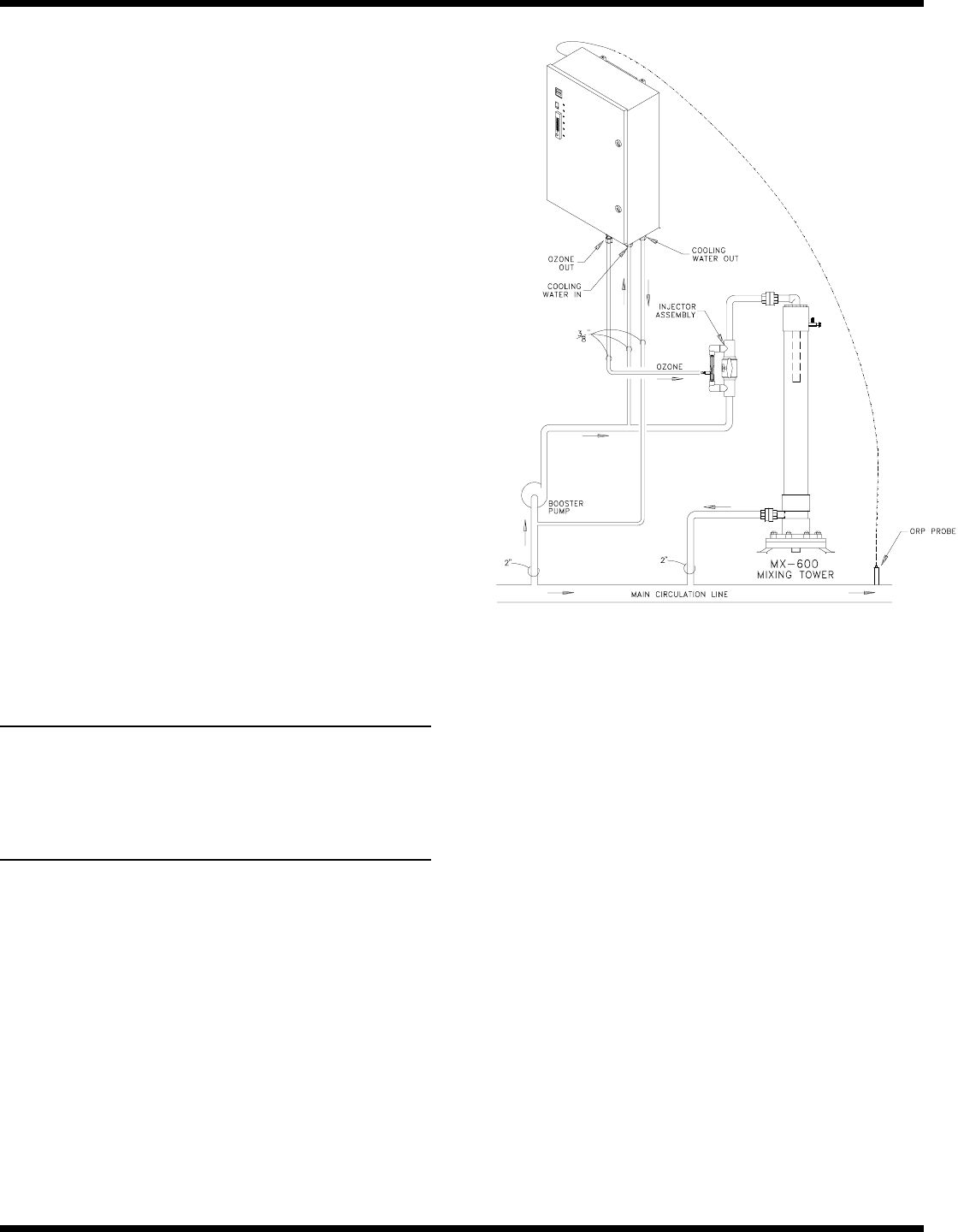
2D-1. Ozone Gas Line
1. Connect ozone tubing to generator outlet fitting.
(3/8" stainless steel compression fitting.)
2. Connect opposite end of ozone tubing to injector
suction port. (Suction port fitting: 3/8" stainless
steel compression fitting.)
See figure 2
.
NOTE: The ozone gas supply line must have a back flow
prevention device (such as a check valve) installed be-
tween the ozone generator cabinet and the point of
injection to prevent water from backing up into the
generator system. An ozone supply check valve is
included with the MX-600-CD system.
2D-2. Cooling Water
Cooling water must be supplied as specified in sec-
tion 1B.
1/4" FPT connections are supplied on the generator.
See figure 2
. Be sure that the tubing is appropriately
matched with the marked inlet and outlet ports. Care-
fully match and connect to water plumbing as shown
in figure 2. Alternate method using connections at in-
jector may be used.
Figure 2: Plumbing Schematic
2E. ORP Sensor Connection
(For optional ORP Controller) Consists of mounting the
ORP probe and routing the sensor cables.
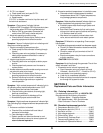
2E-1. ORP Probe Mounting
The sensor should be placed in the water stream at a
point downstream from the ozone injector.
See figure 2
.
1. Locate the point of insertion in the process pipe.
NOTE: Install the ORP probe in a location which
provides easy access for removal and cleaning of
the probe. The probe should be installed such that
the main stream ORP is measured. Locating the
ORP probe upstream of the ozone measures the
"pool" water. Locating the probe downstream of the
ozone measures the ORP of water returning to pool.
2. Install an appropriately sized tee in the process
line or drill and tap a
1
/
2
" FPT hole in the process
pipe as shown in figure 3.
3. Remove the protective cap and apply Teflon tape
to the sensor threads. Thread the sensor into the
fitting or tapped hole. Save the protective sensor
cap for storage.
4. Start the circulation system and check for leaks
around the sensor.