


8
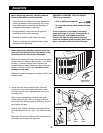
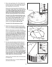
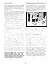
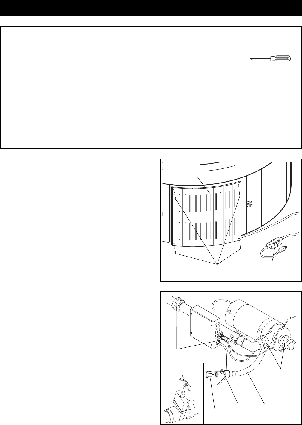
2. Locate the drain hose inside the spa. Close the
valve knob on top of the drain hose. Next, make
sure that the cap is fully tightened onto the end of
the drain hose.
Refer to the inset drawing. Locate the two gate
valves inside the spaÑthere is one gate valve on
each side of the access opening. Make sure that the
gate valves are open.
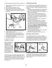
Refer to step 1 above. Re-attach the Access Panel
(2) to the spa with the four #6 x 1 1/4Ó Wood Screws
(7).
Make sure that the two collars on the heater and the
two collars on the pump are tightened.
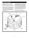
Before beginning assembly, carefully read the
following information and instructions:
¥ Place all parts in a cleared area and remove the
packing materials from the spa shell. Do not dis-
pose of the packing materials until assembly is
completed and the spa is operating.
¥ During assembly, make sure that all parts are
oriented as shown in the drawings.
¥ Read each assembly step before you begin.
¥ Tighten all parts as you assemble them, unless
instructed to do otherwise.
ASSEMBLY REQUIRES THE FOLLOWING
TOOLS (not included):
¥ One (1) phillips screwdriver
¥ You may also need a small amount of soap
or water.
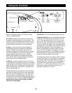
A wire connector is provided on the pump
motor of the spa to connect a minimum No. 8
AWG (804 mm
2
) solid copper conductor
between the spa and any metal equipment,
electrical enclosure made of metal, metal water
pipes, or conduit within five feet of the spa.
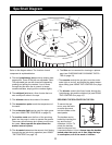
1. Before beginning assembly, make sure that you
have read and understand the information in the
box above and on the previous two pages.
Refer to the drawing on page 6 and locate the slotted
Access Panel (2). Remove the four #6 x 1 1/4Ó Wood
Screws (7) from the Access Panel. Remove the
Access Panel by sliding it down and then pulling the
bottom of it away from the spa. Be careful not to
damage the spa shell.
Remove the end of the power cord and the GFCI from
inside the spa.
Assembly
Power Cord
with GFCI
Drain
Hose
Valve
Knob
Cap
Collars
Collars
7
2
1
2
Gate Valve