


ADJUSTMENTS
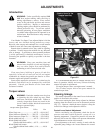
Introduction
WARNING: Unless specifically required, DO
NOT have engine running when servicing or
making adjustments to tractor. Place control
levers in the park brake position and remove
ignition switch key. Repairs or maintenance
requiring engine power should be performed by
trained personnel only. To prevent carbon
monoxide poisoning, be sure proper ventilation
is available when engine must be operated in an
enclosed area. Read and observe safety warnings
in front of manual.
Your Hustler Z or Super Z was adjusted before it left the
factory and was checked during predelivery setup.
However, after start-up and continued use, a certain amount
of break-in wear will cause some adjustments to change.
Remain alert for unusual noises, they could be signaling
a problem. Visually inspect the machine for any abnormal
wear or damage. A good time to detect potential problems
is while performing scheduled maintenance service.
Correcting the problem as quickly as possible is the best
insurance.
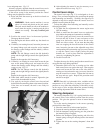
WARNING: Keep your machine clean and
remove heavy deposits of trash and clippings,
they can cause engine fires and hydraulic
overheating as well as excessive belt wear.
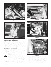
Clear away heavy build-up of grease, oil and dirt,
especially in the area of reservoir and oil and engine
combustion air; minute dust particle are abrasive to close-
tolerance engine and hydraulic assemblies.
Some repairs require the assistance of a trained service
mechanic and should not be attempted by unskilled
personnel. Consult your Hustler service center when
assistance is needed.
Torque values
WARNING: Particular attention must be given
to tightening the drive wheel lug nuts, wheel
motor nuts, and blade spindle bolts. Failure to
correctly torque these items may result in the
loss of a wheel or blade, which can cause serious
damage or personal injury.
Torque values given below:
Ft-lbs. Nm
Wheel (lug) nuts ................................65-75......88.14-101.7
Wheel motor nut (Hustler Z) .........350-375 .....474.6-508.5
Wheel motor nut (Super Z)............290-310 .....393.2-420.4
Blade spindle bolt top........................65-75......88.14-101.7
Blade spindle bolt bottom
(spindle with blade saddle)......65-75......88.14-101.7
Blade spindle bolt bottom
(spindle without blade saddle) ....118...........160.0
It is recommended that these be checked after the first 2
hours of operation, initially and every 50 hours following
removal for repair or replacement.
For engine torque values, see engine owner’s manual.
For all other torques refer to the parts manual for
standard torque chart.
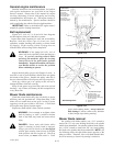
Steering linkage
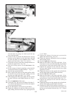
The neutral adjustment for the control levers in the neutral
position is discussed in this section.
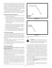
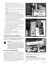
The tractor steering has been factory adjusted to eliminate
creeping when the control levers are in the neutral position
(Fig. 5-1). However, should the tractor begin to creep, the
control lever linkage can be adjusted as follows:
Control Lever Neutral Adjustment
Before considering any adjustment, check the tire air
pressure and make certain hydraulic system oil is at
operating temperature. Unequal tire pressure will cause the
tractor to drift to one side. Refer to tire pressure information
in the Maintenance section of this manual.
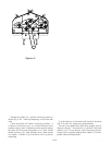
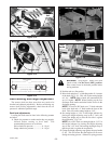
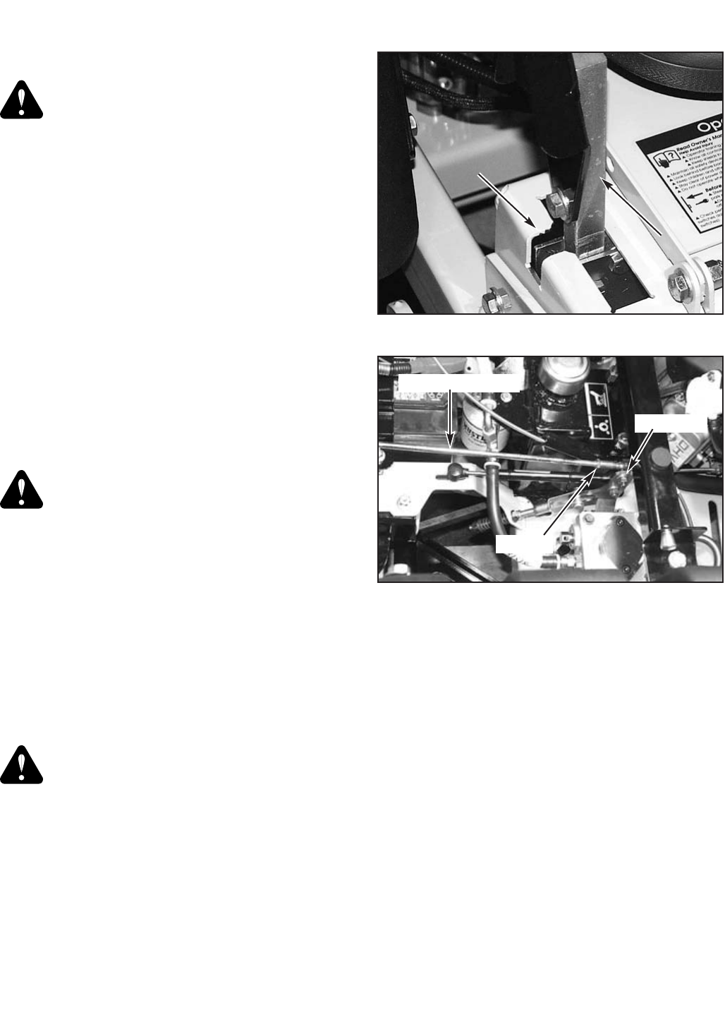
Fine adjustment to the unit’s steering is made with the
adjustable pump linkage rods located between the control
5-1
375527_0406
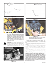
Figure 5-1
PPaarrkk bbrraakkee sslloott
CCoonnttrrooll lleevveerr iinn tthhee
nneeuuttrraall ppoossiittiioonn
Control
lever
Figure 5-2
Pump linkage rod
Pump arm
Jam nut