


111132_0909 5-1
KITS & ATTACHMENTS
Transport wheels kit 601922
A transport wheel kit (601922) is available for the Model 50.
These wheels are used when transporting the unit from one
location to another or when loading on a trailer or truck.
To attach the wheels use the following procedure:
1. Raise the unit using the stand setting procedure outlined
elsewhere in this manual.
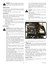
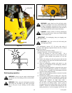
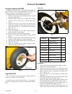
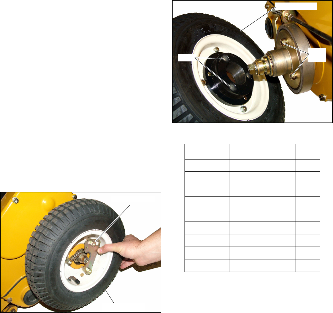
2. Hold the transport wheel with one hand while rotating
clockwise on the locking lever with the other hand.
Fig. 5-1
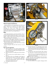
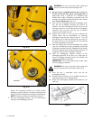
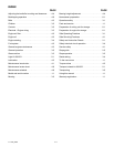
3. Align the three holes in the wheel with the three bolt
heads on the axle hub. Slide the wheel onto the shaft and
release the locking lever. It should lock in place on the
shaft. Fig. 5-2
4. Repeat for other side.
5. Lower the machine per the stand setting procedure
outlined elsewhere in this manual.
To remove the wheels use the following procedure:
1. Raise the unit using the stand setting procedure outlined
earlier.
2. Hold the transport wheel with one hand while rotating
clockwise on the locking lever with the other hand.
3. Slide the wheel off the shaft and release the locking lever.
4. Repeat for other side.
5. Lower the machine per the stand setting procedure
outlined elsewhere in this manual.
Light Kit 601921
This kit provides the necessary parts to install Light Kit
(601921) on a Hustler 50 Greens Mower.
Listed below are parts included in this kit. If any parts are
missing or damaged, please contact the Hustler Parts Depart-
ment.
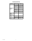
Parts List
Installation
1. Park the unit on a flat surface and shut engine off. Allow
engine to cool before proceeding.
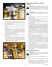
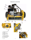
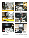
2. Locate the wire clamp at the lower right front of the
engine. Unfold the clamp and remove the braided wiring
harness from the clamp. Re-clamp the remaining wires.
Fig. 5-3 & Fig. 5-4
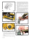
3. Remove the front two nuts that attach the fuel tank to the
engine.Fig. 5-5
4. Attach the mounting bracket and clamp to the engine using
the nuts that were removed in step 3. Fig. 5-6
5. Attach the rubber mount, light and black ground wire to
the mounting bracket using the hardware shown. Fig. 5-2
6. Connect the black ground wire to the engine’s black wire
(comes out of braided wiring harness). Fig. 5-7
7. Connect the light’s red wire to the black wire with two red
stripes. Then, connect the other end of the black wire with
Fig. 5-1
Locking lever
Transport wheel
Fig. 5-2
Part No. Description Qty.
385100791 Light assembly 1
A46650130 Mounting bracket 1
398110050 Rubber mount 1
020900008 Nut 2
027100008 Lock washer 2
026100008 Flat washer 2
385600430 Harness compl 1
385604060 Harness 1
399111960 Clamp 1
Holes
Bolt
heads
Transport wheel