


111132_0909 3-3
when the traction drive is engaged.
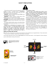
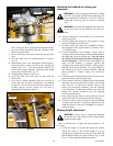
E. Brake lever (Fig. 3-1 & Fig. 3-2) — The brake lever is
mounted off the LH operator handle. This brake has two
levers. The longer lever is pulled to engage the brake.
To set the park brake, pull this long lever back toward the
handlebar until the park brake lever snaps into the locked
position. Release the long brake lever, and the park
brake is set. To release the park brake, pull on the
shorter park brake lever and the long brake lever
returns to the released position
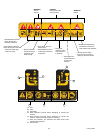
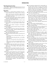
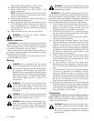
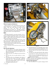
F. Choke control (Fig. 3-3) — The choke is controlled
directly on the engine. As the decal indicates, the choke
is on when the lever is pushed to the forward direction of
the machine, and off when the lever is pulled to the rear.
Choke should only be used when starting the engine, and
shall remain off when in normal operation.
G. Fuel valve (Fig. 3-3) — Push fuel valve lever forward to
open fuel valve and push lever rearward to shut fuel
valve off. IMPORTANT: Fuel valve should be shut off
when engine is not running and machine is stopped.
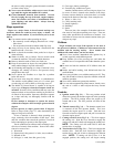
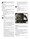
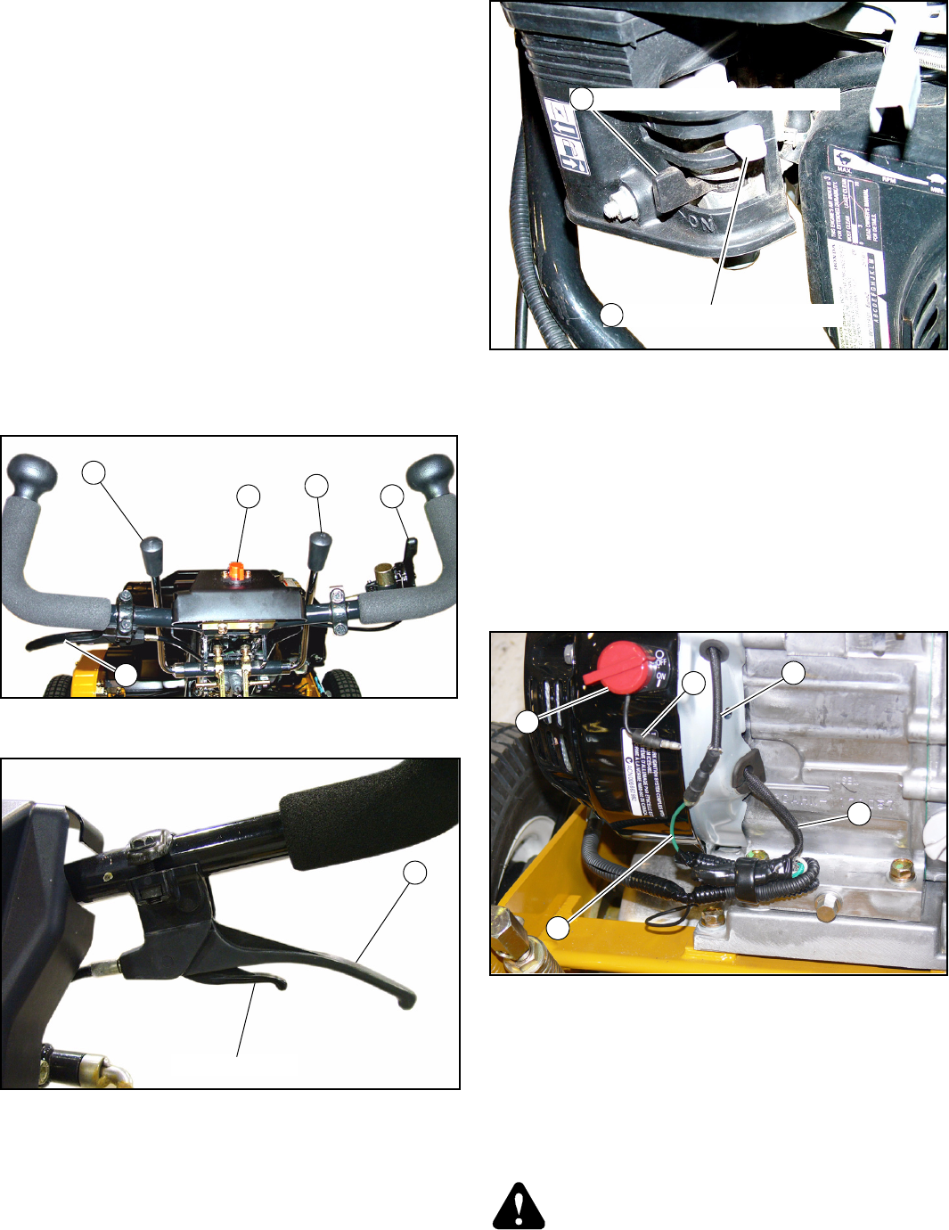
Electrical - Engine wiring
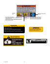
A. Engine switch (Fig. 3-4) — There is an “ON - OFF”
switch located on the front of the engine. This switch is
not used and shall remain in the off position.
B. Wire lead - engine switch (Fig. 3-4) — This wire is not
used and shall remain unplugged.
C. Engine coil kill wire (Fig. 3-4)
D. Ignition switch wire (Fig. 3-4) — This single green wire
connects to the ignition switch located at the operator
handlebars. It is to remain plugged into the female bullet
connector from engine coil kill wire at all times.
E. Braided wire loom - optional light power (Fig. 3-4) —
These wires provide power to the optional light kit.
Leave bundled with the tape in place if light kit is not
installed.
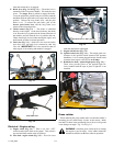
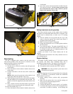
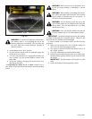
Grass catcher
When attaching the grass catcher make sure that the catcher’s
mounting pins are seated firmly in place on the mower. Make
sure that it is down in the positioning slots as far as it will go and
is not sitting at an angle. Fig. 3-5 & Fig. 3-6
WARNING: Attach the grass catcher prior to starting
the engine to prevent injury. Grass catcher should be
attached to machine at all times when in operation!
Fig. 3-1
Fig. 3-2
D
A
C
B
E
Park brake lever
E
Fig. 3-3
Fig. 3-4
Choke shown in “OFF” position
Fuel valve shown in “OFF” position
G
F
D
A
C
B
E