111782_0910 3-3
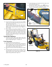
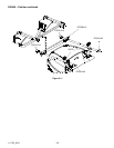
3. Locate the frame support brace onto the tractor’s ROPS
with the short end of the bend facing upwards and to the
rear of the tractor. Figure 3-11
Raise the support brace until the pins from the box
support frame rest inside the notches in the support brace.
Secure in place using the hardware shown. Tighten all
nuts and bolts.
4. Test to make sure the dump mechanism is working
properly. Pull the lift handle towards the operator’s seat
and lift upward. The container’s door should open and the
box should pivot towards the ground. If the dump
mechanism needs adjusted, refer to the Adjusting dump
mechanism section found elsewhere in this manual for
detailed information.
Catcher Box Preparation
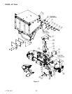
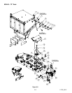
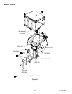
1. Install the box plate support, chute support, thick guide
spacer, thin guide spacer and chute guide to the side of
the box assembly per Figure 3-7 or Figure 3-8
Final Connection
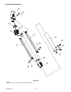
1. Assemble the blower tube per Figure 3-9.
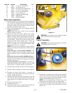
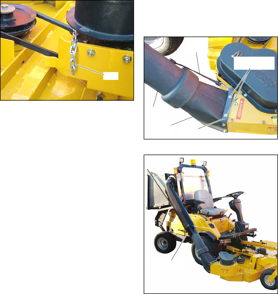
2. Remove the top two nuts and flat washers that attach the
blower housing tube to the blower housing. Slide the
blower tube hook (109716) onto these bolts and secure in
place with the nuts and flat washers. Figure 3-4
3. Slide the lower tube onto the blower housing tube. Figure
3-4
4. Adjust the length of the blower tube assembly until the
top tube flange can slide into the box assembly’s inlet
mount. Secure in place with the chute guide (111904).
Tighten chute guide hardware. Figure 3-6
5. Attach the bungee cord, located on the lower tube, to the
blower tube hook. Figure 3-4
6. Reconnect the negative battery cable. NOTE: Refer to
the Accessing the engine compartment section, found
elsewhere in this manual, for detailed information.
Figure 3-3
Chain
Figure 3-4
Figure 3-5
Remove these nuts
and flat washers
Bungee
strap
109716
Blower
housing
tube
Lower
tube
Tube assembly


