


English-48
ELECTRICAL SYSTEM
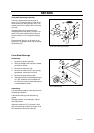
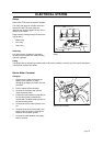
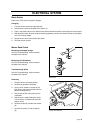
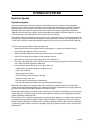
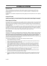
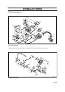
Ignition and Start Switch
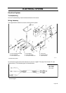
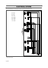
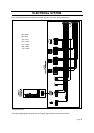
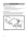
Refer to the “ZTH electrical system” diagram.
Changing
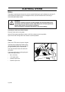
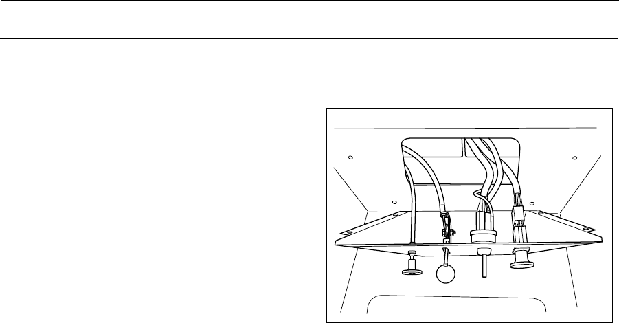
1. Free the control console and pull
forwards.
2. Disconnect the wires at the back of the
ignition switch (10).
3. Remove the ignition key and the rubber
cap (20).
4. Remove the nut (19) and the ignition
switch (10).
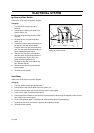
5. Thread the toothed plate connector onto
the throat of the new ignition switch.
Feed the switch into the console from the
rear. Turn the switch so that the single pin
faces towards the blade switch.
6. Start the nut (19) off on its thread and
twist the switch to the correct position in
the console panel. Try the key in the
switch and then tighten the nut.
7. Remove the key and fit the rubber cap
(20). Reinsert the key.
8. Reconnect the wires at the back of the
ignition switch.
9. Refit the control console.
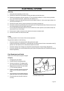
Hour Meter
Refer to the “ZTH electrical system” diagram.
Changing
1. Free the control console and pull forwards.
2. Disconnect the wires at the back of the hour meter (12).
3. Prise the catches apart and remove the hour meter’s locking plate.
4. Pull the hour meter out of the console panel.
5. Ensuring that the numbers are turned to the correct position to be seen by the operator, insert the new
hour meter in the console panel.
6. Fit the locking frame (push in manually and check that the catches have fastened).
7. Connect the two violet wires to the right pin and the black to the left.
8. Refit the control console.
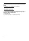
8011-599
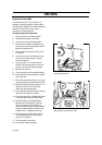
Freeing the control console