


ASSEMBLY
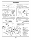
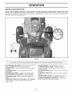
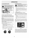
ANTI-SWAY BAR
(s)
; TRANSAXLE
.............................;................... BRACKET (T)
LOCATE D
........ BETWEENREAR
TIRES
TRANSAXLE BRACKET
Fig. 10
NOTE: Depending on model, bracket (T) may be differ-
ent than shown but hole for anti-sway bar will be in same
position/location.
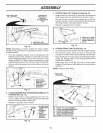
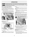
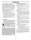
• Pivot the integrated washer end of anti-sway bar (S)
towards mower deck bracket on right side of mower.
Insert integrated washer end of bar into hole in rear
mower bracket (D). Move mower as needed to insert
integrated washer end of bar into rear mower bracket (D).
• Secure with small washer and small retainer spring as
shown.
oSP
Fig. 11
J
/
D. RIGHT SiDE
REAR MOWER
BRACKET
S. ANTI-SWAY BAR
1". TRANSAXLE
BRACKET
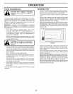
6. ATTACH MOWER SIDE SUSPENSION ARMS (A) TO
CHASSIS (See Fig. 12)
• Position front hole in side suspension arm (A) over
pin on outside of tractor chassis and secure with large
washer and large retainer spring (B).
• Repeat on opposite side of tractor.
Fig. 12
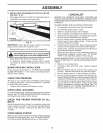
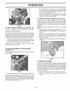
7. ATTACH REAR LIFT LINKS (C) (See Fig. 13)
• Insert rod end of rear lift link (C) into hole (U) in tractor lift
shaft suspension arm and pivot link down to mower.
• Lift rear corner of mower and position slot in link as-
sembly over pin on rear mower bracket (D) and secure
with large washer and large retainer spring.
• Repeat on opposite side of tractor.
I
m,',,' D RGHTSDEREAR
I '_, 'f_-_ ' _ _/_/ : ...... MOWER BRACKET
';_ _ i U HOLE
Fig. 13
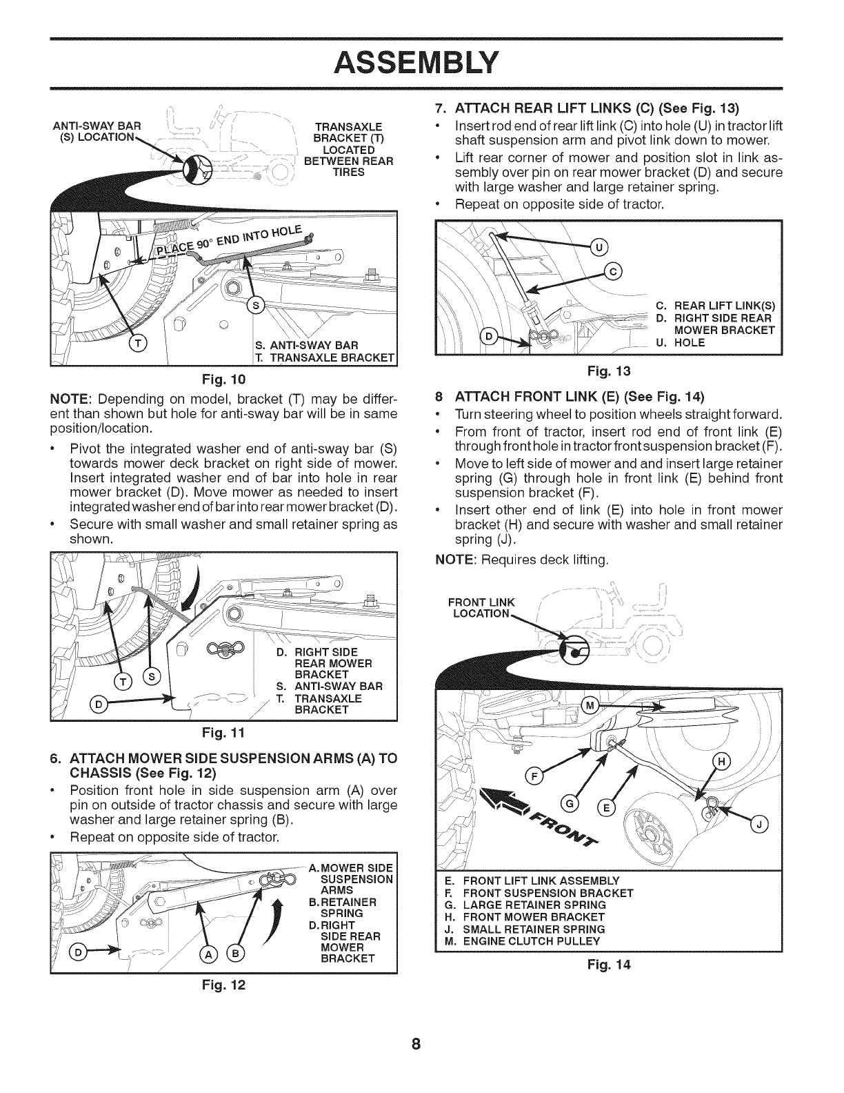
8 ATTACH FRONT LINK (E) (See Fig. 14)
• Turn steering wheel to position wheels straightforward.
• From front of tractor, insert rod end of front link (E)
through front hole in tractor front suspension bracket (F).
• Move to left side of mower and and insert large retainer
spring (G) through hole in front link (E) behind front
suspension bracket (F).
• Insert other end of link (E) into hole in front mower
bracket (H) and secure with washer and small retainer
spring (J).
NOTE: Requires deck lifting.
FRONT LINK
E. FRONT LIFT LINK ASSEMBLY
F. FRONT SUSPENSION BRACKET
G. LARGE RETAINER SPRING
H. FRONT MOWER BRACKET
J. SMALL RETAINER SPRING
M. ENGINE CLUTCH PULLEY
Fig. 14
8