


SERVICE AND ADJUSTMENTS
_ WARNING: TO AVOID SERIOUS iNJURY, BEFORE PERFORMING ANY SERVICE OR ADJUSTMENTS:
Depress brake pedal fully and set parking brake.
" Place attachment clutch in "DISENGAGED" position.
" Turn ignition key to "STOP" and remove key.
" Make sure the blades and all moving parts have completely stopped.
" Disconnect spark plug wire from spark plug and place wirewhere it cannot come incontact with plug.
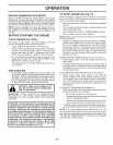
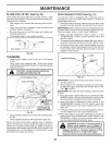
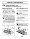
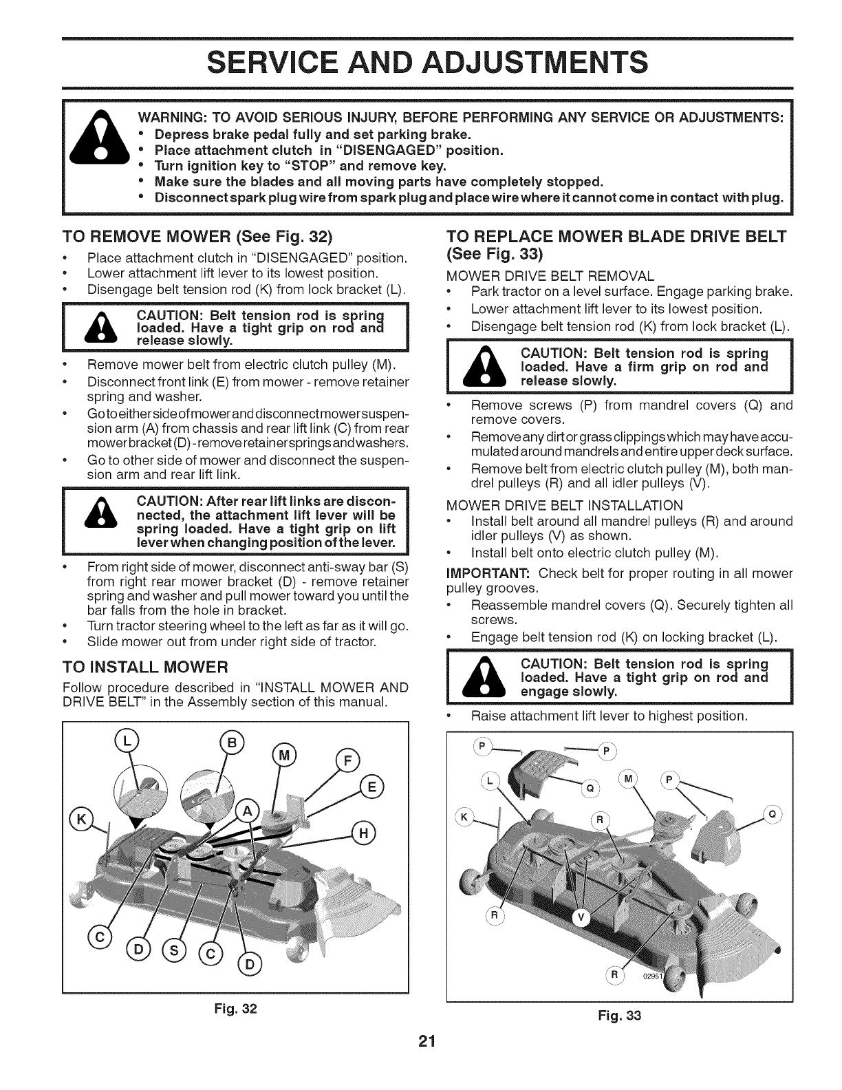
TO REMOVE MOWER (See Fig. 32)
• Place attachment clutch in "DISENGAGED" position.
• Lower attachment lift lever to its lowest position.
• Disengage belt tension rod (K) from lock bracket (L).
= m
CAUTION: Belt tension rod is spring
_lb release slowly.
I loaded. Have a tight grip on rodand I
• Remove mower belt from electric clutch pulley (M).
• Disconnect front link (E) from mower - remove retainer
spring and washer.
• Goto eitherside ofmower anddisconnect mowersuspen-
sion arm (A) from chassis and rear lift link (0) from rear
mower bracket (D)- remove retainersprings andwashers.
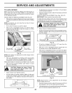
• Go to other side of mower and disconnect the suspen-
sion arm and rear lift link.
&
CAUTION: After rear lift links are discon=
nected, the attachment lift lever will be
spring loaded. Have a tight grip on lift
lever when changing position of the lever.
From right side of mower, disconnect anti-sway bar (S)
from right rear mower bracket (D) - remove retainer
spring and washer and pull mower toward you until the
bar falls from the hole in bracket.
Turn tractor steering wheel to the left as far as itwill go.
Slide mower out from under right side of tractor.
TO INSTALL MOWER
Follow procedure described in "INSTALL MOWER AND
DRIVE BELT" in the Assembly section of this manual.
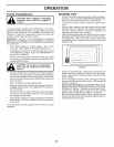
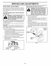
TO REPLACE MOWER BLADE DRIVE BELT
(See Fig. 33)
MOWER DRIVE BELT REMOVAL
• Park tractor on a level surface. Engage parking brake.
• Lower attachment lift lever to its lowest position.
• Disengage belt tension rod (K) from lock bracket (L).
CAUTION: Belt tension rod is spring I
loaded. Have a firm grip on rod and
lrelease slowly,
• Remove screws (P) from mandrel covers (Q) and
remove covers.
• Remove any dirt orgrass clippings which may have accu-
mulated around mandrels and entire upper decksudace.
• Remove belt from electric clutch pulley (M), both man-
drel pulleys (R) and all idler pulleys (V).
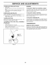
MOWER DRIVE BELT INSTALLATION
• Install belt around all mandrel pulleys (R) and around
idler pulleys (V) as shown.
• Install belt onto electric clutch pulley (M).
iMPORTANT." Check belt for proper routing in all mower
pulley grooves.
• Reassemble mandrel covers (Q). Securely tighten all
screws.
• Engage belt tension rod (K) on locking bracket (L).
&
• Raise attachment lift lever to highest position.
Fig. 32
21
Fig. 33