


ASSEMBLY
Your new tractor has been assembled at the factory with exception of those parts left unassembled for shipping purposes.
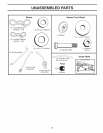
TOOLS REQUIRED FOR ASSEMBLY
A socket wrench set will make assembly easier. Standard
wrench sizes are listed.
(2) 7/16" wrenches Utility knife
(1) 1/2" wrench Tire pressure gauge
(1) 3/4" wrench Pliers
(1) 3/4" socket w/drive ratchet
(1) 9/16" wrench Flashlight
When right or left hand ismentioned inthis manual, itmeans
when you are in the operating position (seated behind the
steering wheel).
TO REMOVE TRACTOR FROM CARTON
UNPACK CARTON
• Remove all accessible loose parts and parts cartons
from carton.
• Cut along dotted lines on all four panels of carton.
Remove end panels and lay side panels flat.
• Remove mower and packing materials.
• Check for any additional loose parts or cartons and
remove.
BEFORE REMOVING TRACTOR FROM
SKID
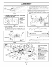
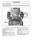
TO CHECK BATTERY (See Fig. 1)
• Lift hood to raised position.
NOTE: If this battery is put into service after month and
year indicated on label (label is located between terminals)
charge battery for minimum of one hour at 6-10 amps.
(See "BATTERY" in Maintenance section of this manual
for charging instructions).
• For battery and battery cable installation see "RE-
PLACING BATTERY"in the "Service and Adjustments"
section in this manual.
/
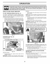
LABEL
Fig. 2
NOTE: You may now roll your tractor off the skid. Follow
the appropriate instruction below to remove the tractor
from the skid.
_k WARNING: Before starting, read, understand and follow
all instructions in the Operation section of this manual. Be
sure tractor is in a well-ventilated area. Be sure the area in
front of tractor is clear of other people and objects.
TO ROLL TRACTOR OFF SKID (See Op=
eration section for location and function of
controls)
• Raise attachment lift lever to its highest position.
• Release parking brake by depressing brake pedal.
• Place freewheel control in disengaged position to dis-
engage transmission (See "TO TRANSPORT" in the
Operation section of this manual).
• Roll tractor forward off skid.
Continue with the instructions that follow.
TO INSTALL MOWER AND DRIVE BELT
(See Figs. 3 = 15)
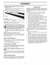
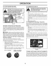
1. SET PARKING BRAKE LEVER AND LOWER AT=
TACHMENT LIFT LEVER (See Fig. 3 and 4)
• Depress clutch/brake pedal all the way down and hold.
• Pull parking brake lever up and hold, release pressure
from clutch/brake pedal, then release parking brake
lever. Pedal should remain in brake position. Ensure
parking brake will hold tractor secure.
\/
Fig. 1
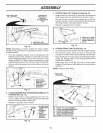
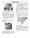
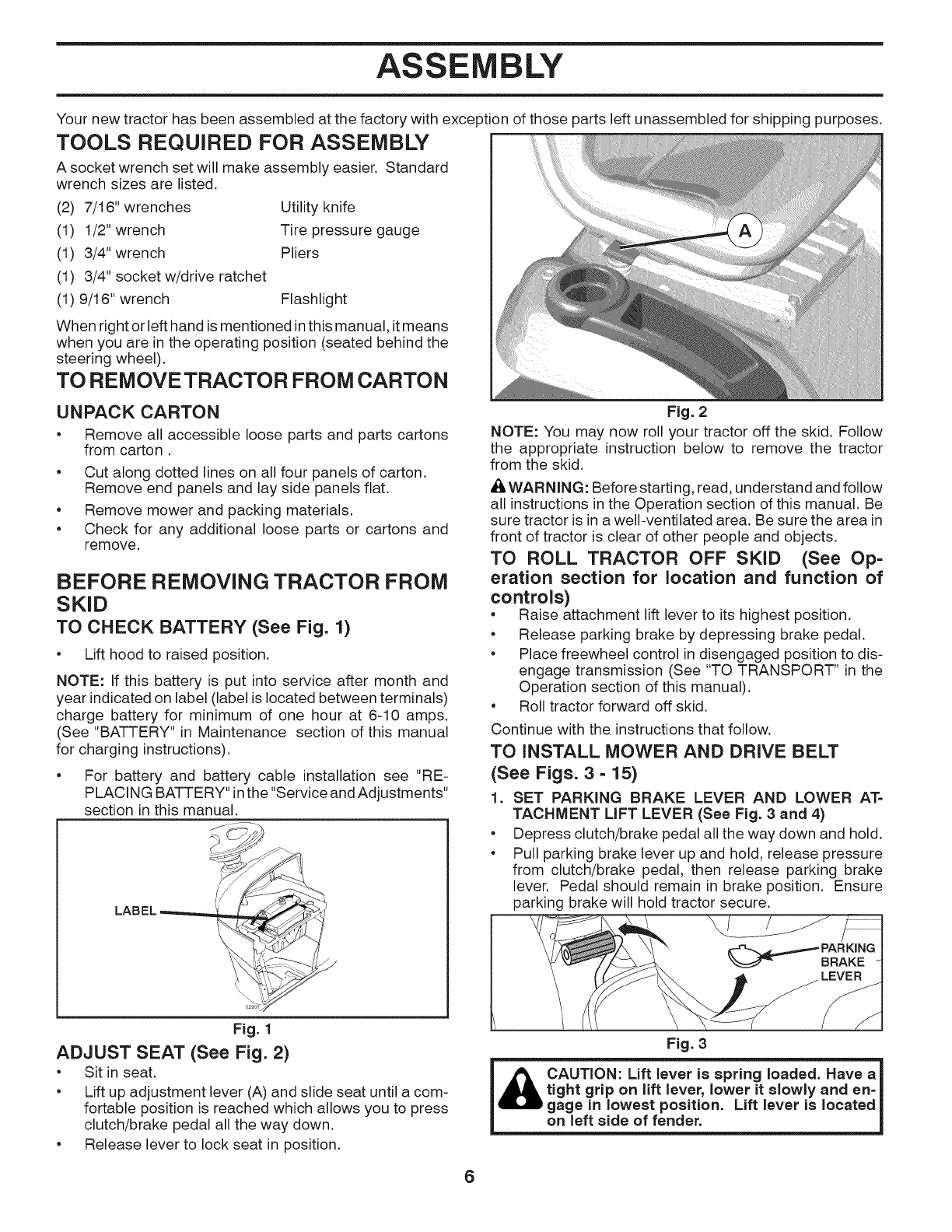
ADJUST SEAT (See Fig. 2)
• Sit in seat.
• Lift up adjustment lever (A) and slide seat until a com-
fortable position is reached which allows you to press
clutch/brake pedal all the way down.
• Release lever to lock seat in position.
6
Fig. 3
CAUTION: Lift lever is spring loaded. Have a
tight grip on lift lever, lower it slowly and en=
gage in lowest position. Lift lever is located
on left side of fender.