


5
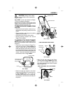
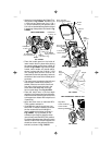
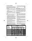
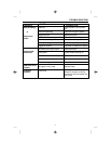
• Attach the front wheels to the Edger/Trim-
mer shown in Fig. 5-ASSY with a 5/16-18
x 4.50 inch hex head screw, four 11/32 x
11/16 inch flatwashers, two spacers and a
5/16-18 hex head wide flange locknut found
in parts bag. Note position of wheels in Fig.
5-ASSY.
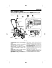
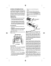
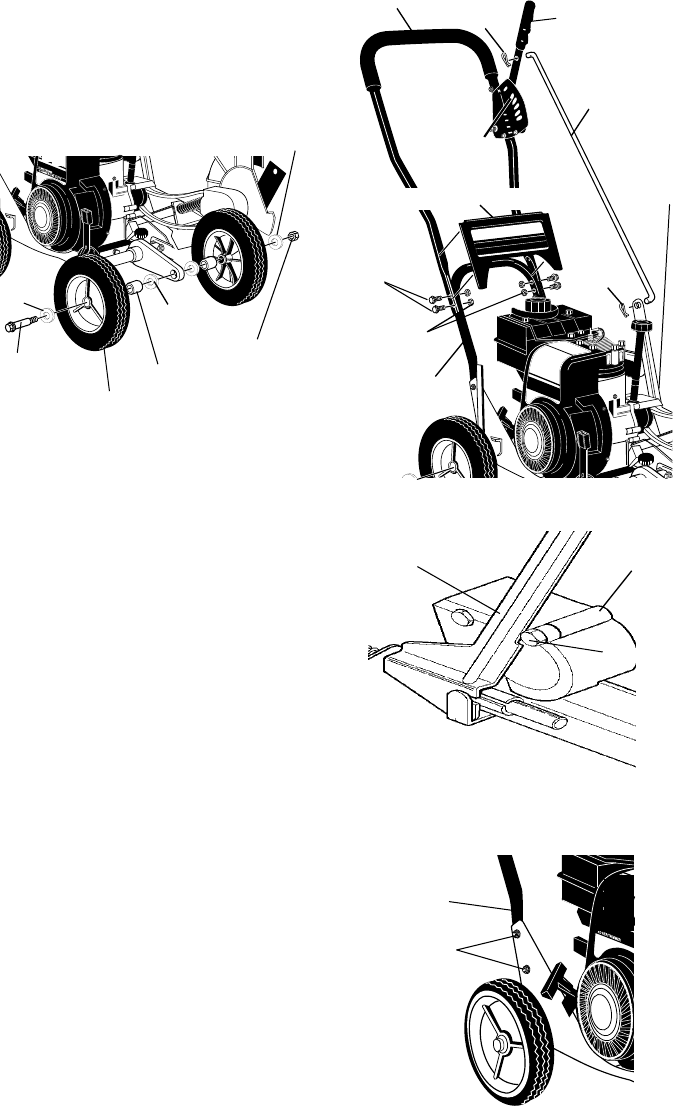
• Place the handle panel on the inside of
lower handle. Hold in place while placing
the upper handle on the lower handle as
shown in Fig. 6-ASSY. Align holes in upper
handle, lower handle and handle panel,
secure in place with four 5/16-18 x 1-5/8
inch carriage bolts and four 5/16-18 hex
head locknuts found in parts bag. Locknuts
should be to the inside of the handle panel
as shown.
• The clutch lever is located on the left hand
side of upper handle when properly in-
stalled. Insert one end of the control rod
from left to right through the hole in the
clutch lever and attach with a hair pin
found in parts bags. See Fig. 6-ASSY.
• Place the clutch lever in the first depth
selection hole (forward) and insert the other
end of the control rod through the hole in the
quill support arm. Attach with hairpin found
in parts bag.
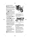
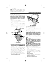
• Move the clutch lever to rearmost NEU-
TRAL position and latch in.
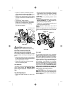
• If it is difficult to get the clutch lever into
NEUTRAL, it may be necessary to loosen
the four screws and nuts holding the
lower handles to the frame as shown in
Fig. 8-ASSY. Pry up (forward) on the
handles only enough to allow the clutch
lever to freely enter the NEUTRAL position.
Re-tighten nuts and screws. When the clutch
lever is in NEUTRAL the quill support arm
should be close to the spacer and screw
behind it as shown in Fig. 7-ASSY.
Right Side
Lower Handle
Lower Handle
Mounting Bolts
Quill
Support
Arm
Spacer
Screw
FIG. 7-ASSY
Flatwasher
11/32x11/16
Flatwasher
11/32x11/16
Flatwasher
11/32x11/16
Spacer
(1.39 Inch Long)
5/16-18x4.50
Hex Head Screw
Wheel
5/16-18 Wide
Flange Locknut
FIG. 5-ASSY
FIG. 6-ASSY
FIG. 8-ASSY
VIEW FROM FRONT
5/16-18 Hex
Head Locknut
Hair Pin
Control
Rod
Clutch
Lever
Hair Pin
First Depth
Selection
Handle Panel
5/16-18x1-5/8
Carriage Bolts
Upper Handles
(in operating position)
Quill
Support
Arm
Lower
Handle
VIEW FROM RIGHT SIDE OF UNIT