


11
CAUTION: Always stop the engine
and disconnect the spark plug wire before
making any repairs to the Edger/Trimmer.
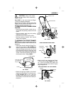
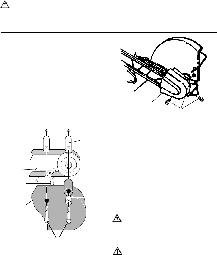
SERVICE AND ADJUSTMENTS
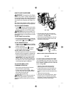
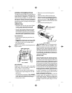
Belt
Guard
Belt Guard
Screws
FIG. 2-SERV & ADJ
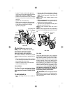
BLADE REPLACEMENT
The cutting blade is subject to wear and
damage such as nicks and dents. This will not
generally affect its function.
This blade is specially designed to not require
sharpening. Do not attempt to sharpen this
blade. The blade is reversible. If the nicks and
dents are excessive, remove the blade, turn it
around and reinstall. This will provide a fresh
cutting edge. The blades should be replaced
if both sides are worn and damaged. If any
cracks are evident, replace the blade imme-
diately.
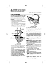
CAUTION: When removing or tighten-
ing the blade nut, always use the method
shown in Fig. 3- SERV & ADJ. The holding
wrench must always be positioned on the nut
behind the cutting blade.
CAUTION: Do not attempt to sharpen
this blade. Sharpening could damage it and
cause it to break, which may further result in
injury to yourself or a bystander.
To replace the blade, do the following:
• Always wear gloves when handling the
blade.
• Disconnect spark plug wire.
• Remove the 1/2-20 locknut shown in Fig. 3-
SERV & ADJ securing the blade to the
drive shaft.
• Remove the blade.
• Install the new blade and reinstall nut.
Tighten the nut securely.
• Reconnect the spark plug wire.
V-BELT REPLACEMENT
Your Edger/Trimmer is equipped with a V-belt
made of a special compound. If the belt be-
comes worn or breaks, replace it with an
orignal equipment belt as shown in the Repair
Parts section of this manual. Never use a
substitute.
• Disconnect the spark plug wire.
• Put the clutch lever back or up to release the
tension from the belt.
• Remove the two top screws from the engine
pulley cover as shown in Fig 1-SERV&
ADJ and remove the cover. Make sure you
do not lose the spacer on the rear screw.
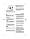
Engine Pulley
Cover Screws
Engine
Pulley Cover
Screw
Spacer
Engine
Pulley
V-Belt
Front
Screw
Belt
Guide
• Remove the front screw securing the belt
guide as shown in Fig. 1-SERV& ADJ , to
the engine. Swing the belt guide away from
the belt.
• Remove the three screws from the belt
guard as shown in Fig. 2- SERV & ADJ.
• Remove the belt from the engine and quill
assembly pulleys and install the new belt.
• Install and secure front belt guard.
• Secure the belt guide loosened earlier.
• Reinstall the engine pulley cover and re-
connect the spark plug wire.
FIG. 1-SERV & ADJ
Control
Lever
Stop
Spacer