


4
ASSEMBLY
CAUTION
: Always wear safety
glasses or eye shields while assembling
Edger/Trimmer.
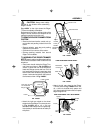
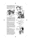
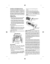
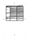
Fig.1-ASSY to the right shows the Edger/
Trimmer completely assembled.
References to the right or left hand side of the
Edger/Trimmer are from the viewpoint of the
operator's position behind the unit.
TO REMOVE EDGER/TRIMMER FROM
CARTON
• Remove the lower handle, control rod, up-
per handle and packing material from the
carton.
• Remove wheels, parts bag and packing
material from the carton.
• Cut down all four corners of the carton.
• Remove packing material from around
Edger/Trimmer blade.
TO ASSEMBLE THE EDGER/TRIMMER
NOTE
: Lower handle should be attached first
as it is difficult to attach lower handle with the
wheels on.
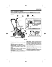
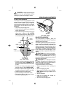
• Place lower handle inside the Edger/Trim-
mer frame as shown in Fig. 2-ASSY and
secure in place with four 5/16-18x5/8 hex
head wide flange screws and four 5/16-18
hex head locknuts found in parts bag. Hold
back on the lower handle as you tighten the
screws. Locknuts should be on the inside of
the frame as shown in Fig. 2-ASSY.
Control Rod
Blade Guard
Clutch Lever
Upper
Handle
Handle
Panel
Starter
Handle
Knob
Blade
Lower
Handle
FIG. 1-ASSY
Frame
Wheel
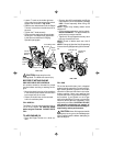
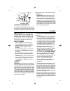
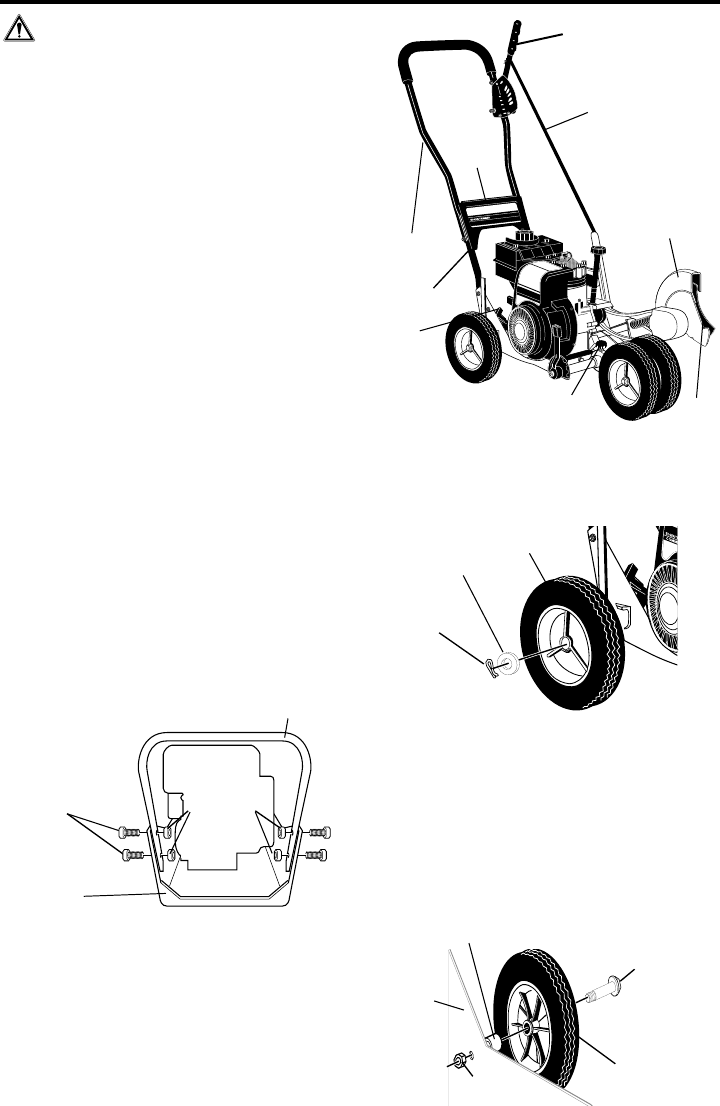
VIEW FROM INSIDE LEFT REAR WHEEL
Spacer
(.70 inch long)
3/8-16 Hex Head
Whiz-lock Nut
Shoulder Bolt
3/8-16x1.40
FIG. 4-ASSY
5/16-18
Hex Head
Locknuts
Lower Handle
5/16-18 X 5/8 inch
hex head wide
flange Screws
Frame
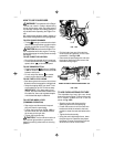
• Attach the right rear wheel to the wheel
support rod of the Edger/Trimmer as shown
in Fig. 3-ASSY with a 1/2 x 3/4 inch
flatwasher and cotter pin found in parts bag.
Insert cotter pin and bend ends of cotter pin
with pliers.
FIG. 2-ASSY
• Attach the left rear wheel to the Edger/
Trimmer shown in Fig. 4 -ASSY with a 3/8-
16 x 1.40 inch shoulder bolt, spacer and
3/8-16 hex head whiz lock nut found in parts
bag and tighten nut.
Wheel
Flatwasher
1/2x3/4 inch
Cotter Pin
FIG. 3-ASSY
VIEW FROM RIGHT REAR WHEEL