


16
SETUP AND ADJUSTMENTS
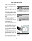
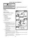
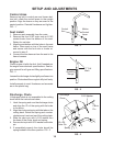
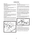
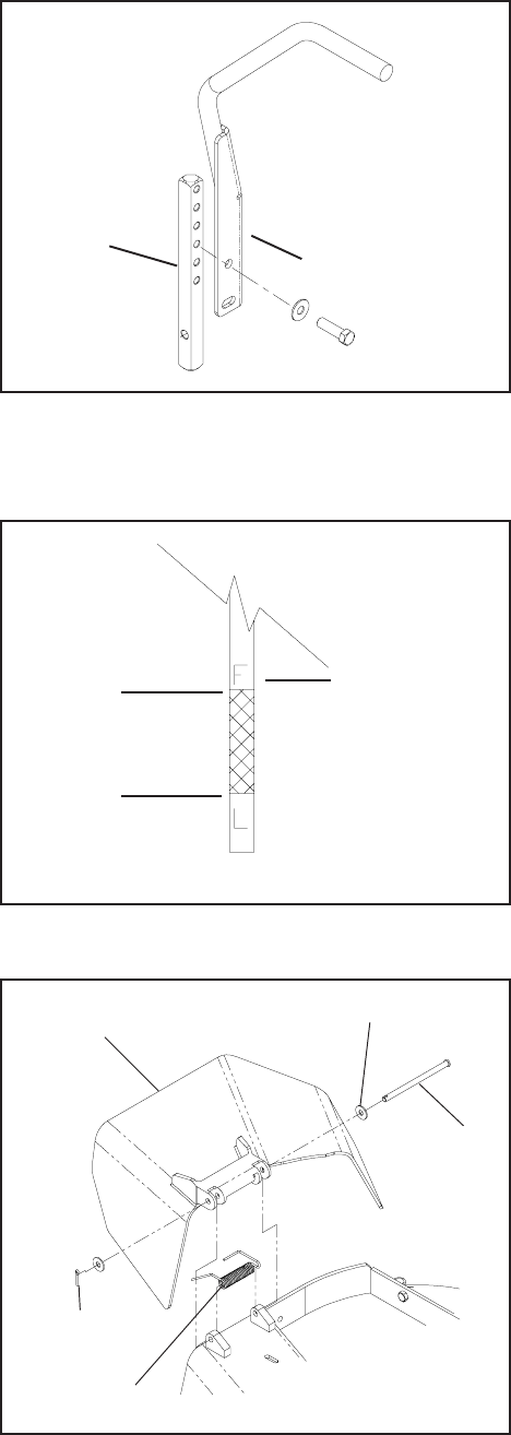
Control Arms
Remove top bolt in control arm and loosen bot-
tom bolt, rotate the control levers to the upright
position. Align the levers so they are even in the
neutral position. Reinstall hardware and tighten.
FIG - 1
Seat Install
1. Remove seat assembly from the crate.
2. Remove the four 5/16C nyloc nuts or 5/16C
studed knobs from the bottom of the seat.
Retain for use later.
3. Align the seat bottom with the holes in the seat
frame. Place seat on top of the seat frame
and secure with the four nuts or knobs re-
moved in step 2.
4. Connect the wire harness from the seat to the
frame harness.
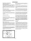
Engine Oil
Check engine oil with dip stick. Add if needed per
the engine manufactures specifications. See en-
gine manual for oil type and filling specifications.
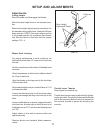
FIG - 2
Loosen the discharge chute slightly and lower into
position. Chute should be snug but still pivot freely.
Install armrests to seat. Hardware and armrests
are in the plastic bag.
Motion
Control
Lever
Control
Arm
“F” Full
Mark
Operating
Range
FIG - 1
FIG - 2
FIG - 3
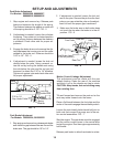
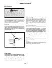
Discharge Chute
If discharge chute is not assembled to the cutting
deck follow the instructions below.
1. Hook the spring end over the discharge chute
and align the I.D. of the spring with the holes
in the chute.
2. Align the chute and spring with the tabs on the
cutting deck. Rotate the spring end counter-
clockwise so it rests on top of the cutting deck.
3. Slide the clevis pin with a 5/16 washer thru
the hoes of the chute, deck and spring.
4. Secure clevis pin with 5/16 washer and cotter
pin.
5. If assembled properly the chute should be
spring loaded in the down position. FIG - 3
Discharge
Chute
5/16 Washer
Clevis
Pin
1/2 x 3/4
Cotter Pin
Spring