


7
FIG. 4
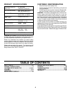
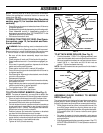
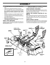
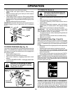
TO ATTACH FRONT BUMPER (See Fig. 4)
NOTE: For ease of assembly, you may wish to obtain the
assistance of another person for mounting bumper to tractor.
• Press or tap the end caps into ends of bumper tube.
• The existing top screw and the existing front screw must
be removed from both sides and discarded.
• On both sides of chassis, position extension bracket as
shown and loosely assemble to rear chassis hole with
supplied 3/8-16 x 1-1/4 bolt. Do not tighten the brackets.
Allow them to hang from the chassis.
• Position bumper and extension brackets so brackets
can be slid inside flattened ends of bumper.
• Slide bumper onto brackets and pivot upwards to align
center holes in extension brackets and tractor chassis.
• With holes aligned, install additional bolts.
• Tighten all four (4) bolts securely.
FRONT
SUSPENSION
BRACKET
SUPPLIED
CARRIAGE
BOLT
BUMPER
END CAP
Slide Onto Exten-
sion Brackets And
Pivot Upwards
SUPPLIED
CARRIAGE
BOLT
EXTENSION
BRACKET
WASHER
SUPPLIED LOCKNUT
SUPPLIED
LOCKNUT
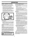
ASSEMBLE GAUGE WHEELS TO MOWER
DECK (See Fig. 6)
The gauge wheels are designed to keep the mower deck in
proper position when operating mower. Be sure they are
properly adjusted to ensure optimum mower performance.
• Slide gauge wheel bar down into bracket channel, Be
sure that gauge wheel bar aligning holes are on top.
Assemble gauge wheels as shown using shoulder bolts,
3/8 washers and 3/8-16 center locknuts and tighten
securely.
• For ease of mower to tractor assembly, raise gauge
wheels to highest position and retain with clevis pins and
spring retainers.
• Adjust gauge wheels before operating mower. See “TO
ADJUST GAUGE WHEELS” in the Operation section of
this manual.
ASSEMBLY
NOTE: You may now roll or drive your tractor off the skid.
Follow the appropriate instruction below to remove the
tractor from the skid.
TO ROLL TRACTOR OFF SKID (See Operation
section, page 12, for location and function of
controls)
• Press lift lever plunger and raise attachment lift lever to
its highest position.
• Release parking brake by depressing clutch/brake pedal.
• Place freewheel control in freewheeling position to
disengage transmission (See “TO TRANSPORT” in the
Operation section of this manual).
• Roll tractor forward off skid.
TO DRIVE TRACTOR OFF SKID (See Opera-
tion section, page 12, for location and func-
tion of controls)
WARNING: Before starting, read, understand and fol-
low all instructions in the Operation section of this manual.
Be sure tractor is in a well-ventilated area. Be sure the area
in front of tractor is clear of other people and objects.
• Be sure all the above assembly steps have been
completed.
• Check engine oil level and fill fuel tank with gasoline.
• Place freewheel control in "transmission engaged" po-
sition.
• Sit on seat in operating position, depress clutch/brake
pedal and set the parking brake.
• Place motion control lever in neutral (N) position.
• Press lift lever plunger and raise attachment lift lever to
its highest position.
• Start the engine. After engine has started, move throttle
control to idle position.
• Release parking brake.
• Slowly move the motion control lever forward and slowly
drive tractor off skid.
• Apply brake to stop tractor, set parking brake and place
motion control lever in neutral position.
• Turn ignition key to "OFF" position.
Continue with the instructions that follow.
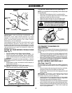
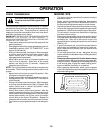
TO ATTACH NOSE ROLLER (See Fig. 5)
• Position brackets, 17/32 x 7/8 x 16 gauge washers, and
nose roller between deck mounting brackets as shown.
Be sure to position brackets on correct side, as shown.
• Install 3/8-16 x 1 hex bolts and 3/8-16 lock nuts as
shown. Tighten hardware securely.
NOTE: Be sure bracket tabs are positioned in tab holes in
deck brackets.
NOSE ROLLER
“B”
BRACKET
TAB
WASHER
TAB
HOLE
LOCK NUT
“A” BRACKET
TAB
FIG. 5
HEX BOLT