


24
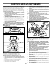
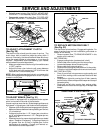
TO REPLACE MOTION DRIVE BELT
(See Fig. 32)
Park the tractor on level surface. Engage parking brake. For
ease of service there is a belt installation guide decal on
bottom of left footrest.
• Remove mower (See “TO REMOVE MOWER” in this
section of this manual.)
BELT REMOVAL -
• Engage parking brake (creates slack in belt).
• Remove belt from clutching and fan idler pulleys.
• Loosen belt keeper above transaxle pulley.
• Remove belt from transaxle pulley.
• Remove belt from engine pulley and front V-idler pulley.
• Pull belt out of all belt keepers and remove from tractor.
BELT INSTALLATION -
• Place V part of belt into grooves on engine pulley and
front V-idler, making sure to route belt inside of all belt
keepers.
• Route belt on right side, coming from V-idler, towards
back of tractor, above midspan belt keeper and to top of
transaxle pulley.
• Route belt on left side, coming from engine pulley,
towards back of tractor and through loop in midspan belt
keeper.
TRACTOR V-BELT DRIVE SCHEMATIC
VIEWED FROM L.H. SIDE OF TRACTOR
V-IDLER
ENGINE
PULLEY
BELT
TWISTS
BELT
KEEPER
BELT
KEEPER
V-IDLER
AS VIEWED FROM BOTTOM
ABOVE BELT
KEEPER
TRANSAXLE
PULLEY
CLUTCHING
FLAT IDLER
CLUTCHING
IDLER
BELT
KEEPER
ENGINE
PULLEY
FAN
IDLER
FIG. 32
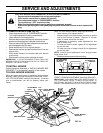
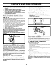
TO ADJUST BRAKE (See Fig. 31)
Your tractor is equipped with an adjustable brake system
which is mounted on the side of the transaxle.
If tractor requires more than six (6) feet stopping distance at
high speed in highest gear, then brake must be adjusted.
• Depress clutch/brake pedal and engage parking brake.
• Measure distance between brake operating arm and nut
“A” on brake rod.
• If distance is other than 1-1/2", loosen jam nut and turn
nut “A” until distance becomes 1-1/2". Retighten jam nut
against nut “A”.
• Road test tractor for proper stopping distance as stated
above. Readjust if necessary. If stopping distance is
still greater than six (6) feet in highest gear, further
maintenance is necessary. Contact your nearest au-
thorized service center/department.
1-1/2"
OPERATING
ARM
WITH PARKING BRAKE “ENGAGED”
NUT “A”
JAM NUT
FIG. 31
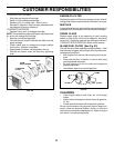
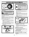
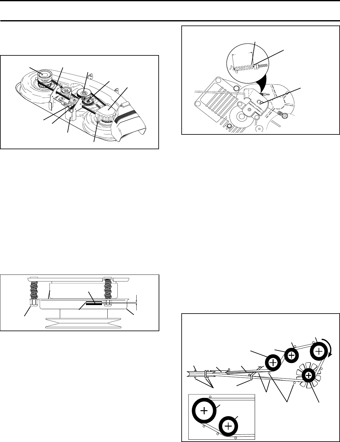
TO ADJUST ATTACHMENT CLUTCH
(See Fig. 30)
The electric clutch should provide years of service. The
clutch has a built-in brake that stops the pulley within 5
seconds. Eventually, the internal brake will wear which may
cause the mower blades to not engage, or, to not stop as
required. Adjustments should be made by your nearest
authorized service center/department.
• Make sure attachment clutch and ignition switches are
in “OFF” position.
• Adjust the three nylon locknuts until space between
clutch plate and rotor measures .012" at all three slot
locations cut in side of brake plate.
NOTE: After installing a new electric clutch, run tractor at full
throttle and engage and disengage electric clutch 10 cycles
to wear in clutch plate.
ROTOR
CLUTCH PLATE
.012"
NYLON
LOCKNUT (3)
SLOT (3)
BRAKE
PLATE
FIG. 30
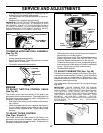
SECONDARY
IDLER ARM
L.H.
MANDREL
MOWER BLADE
DRIVE BELT
CENTER
MANDREL
IDLER
PULLEY
R.H.
MANDREL
COVER
SPRING
SWAY-BAR
BRACKET
SCREW
FIG. 29
SERVICE AND ADJUSTMENTS
• Reinstall mower to tractor (See “INSTALL MOWER AND
DRIVE BELT” in the Assembly section of this manual).
• Reassemble mower drive belt (See “TO REPLACE
MOWER DRIVE BELT” in this section of this manual).