


23
SERVICE AND ADJUSTMENTS
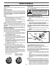
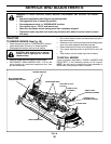
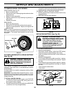
TO CHECK AND ADJUST BRAKE
(See Fig. 25)
Your tractor is equipped with an ad just able brake system
which is mounted on the right side of the transaxle.
If tractor requires more than fi ve (5) feet to stop at highest
speed in high est gear on a level, dry concrete or paved
surface, then brake must be checked and ad just ed.
TO CHECK BRAKE
• Park tractor on a level, dry concrete or paved surface,
depress clutch/brake pedal all the way down and en-
gage parking brake.
• Place gear shift lever in neutral (N) position.
The rear wheels must lock and skid when you try to manually
push the tractor forward. If the rear wheels rotate, the brake
needs to be adjusted or the pads need to be replaced.
TO ADJUST BRAKE
• Depress clutch/brake pedal all the way down and en-
gage parking brake.
• Measure distance between brake operating arm and
nut “A” on brake rod.
• If distance is other than 1-3/4", loos en jam nut and turn
nut “A” until dis tance becomes 1-3/4". Re tight en jam
nut against nut “A”.
• Road test tractor for proper stopping distance as stated
above. Readjust if nec es sary. If stopping distance is
still greater than fi ve (5) feet in high est gear, further
main te nance is nec es sary. Replace brake pads or
contact a qualifi ed service center.
01555
WITH PARKING BRAKE “ENGAGED”
NUT “A”
JAM NUT
OPERATING
ARM
FIG. 25
1-3/4”
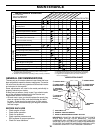
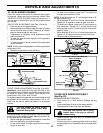
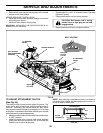
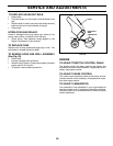
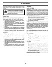
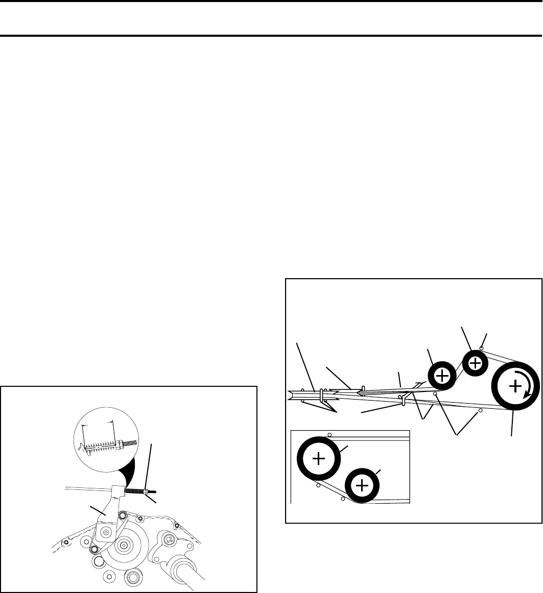
TO REPLACE MOTION DRIVE BELT
(See Fig. 26)
Park the tractor on level surface. Engage parking brake.
For ease of service there is a belt installation guide decal
on bottom of left footrest. It is not necessary to remove
mower.
BELT REMOVAL -
• Engage parking brake (creates slack in belt).
• Remove mower drive belt from electric clutch pulley
only (See “TO REPLACE MOWER DRIVE BELT” in
this section of this manual).
1428
BELT
KEEPER
ENGINE
PULLEY
V-IDLER
ENGINE
PULLEY
CLUTCHING
FLAT IDLER
CLUTCHING
IDLER
BELT
KEEPER
BELT
TWISTS
ABOVE MIDSPAN
BELT KEEPER
BELT
KEEPER
TRANS AX LE
PULLEY
V-IDLER
AS VIEWED FROM BOTTOM
FIG. 26
TRACTOR V-BELT DRIVE SCHEMATIC
VIEWED FROM L.H. SIDE OF TRACTOR
• Roll motion drive belt off transaxle pulley.
• Roll belt off clutching idler pulleys, then off engine pul-
ley and front V-idler pulley.
• Pull belt out of all belt keepers.
BELT INSTALLATION -
• Place V part of belt into grooves on engine pulley and
front V-idler, making sure to route belt inside of belt
keepers.
• Put belt coming from V-idler above midspan belt keep er,
then onto clutching idler pulleys as shown.
• Make sure V part of belt engages V-idler.
• Place belt around transaxle pulley, beginning at top.
V part of belt should engage transaxle pulley.
• Place long lower section of belt through loop in midspan
belt keeper.
• Check to be sure belt is on proper side of all belt keep-
ers.
• Reinstall mower drive belt onto electric clutch pulley.
IMPORTANT: CHECK BRAKE ADJUSTMENT.
TO AD JUST STEER ING WHEEL ALIGN-
MENT
If steering wheel crossbars are not horizontal (left to right)
when wheels are positioned straight forward, remove steer-
ing wheel and reassemble per instructions in the Assembly
section of this manual.
FRONT WHEEL TOE-IN/CAMBER
The front wheel toe-in and camber are not adjustable on
your tractor. If damage has occurred to affect the front
wheel toe-in or camber, contact your nearest authorized
service center/department.