


21
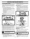
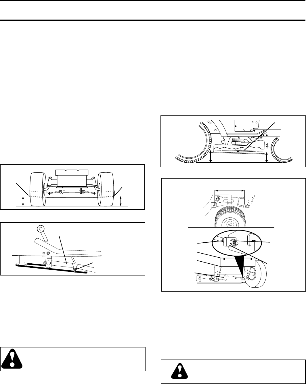
BOTH FRONT PLATE LINKS MUST BE
EQUAL IN LENGTH
TRUN NION
FRONT PLATE
AS SEM BLY
NUT “C”
NUT “D”
FIG. 22
SERVICE AND ADJUSTMENTS
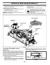
FIG. 19
GROUND LINE
BOTTOM EDGE
OF MOWER
TO GROUND
SUSPENSION ARM
LIFT LINK
AD JUST MENT NUT
AA
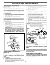
FIG. 20
“B”
FIG. 21
“B”
BLADE
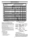
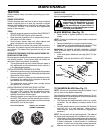
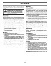
FRONT-TO-BACK ADJUSTMENT (See Figs. 21 and 22)
IMPORTANT: DECK MUST BE LEVEL SIDE-TO-SIDE. IF THE
FOLLOWING FRONT-TO-BACK AD JUST MENT IS NECESSARY,
BE SURE TO ADJUST BOTH FRONT LINKS EQUALLY SO
MOWER WILL STAY LEVEL SIDE-TO-SIDE.
To obtain the best cutting re sults, the mower blades should
be adjusted so the front tip is ap prox i mate ly 1/8" to 1/2"
lower than the rear tip when the mower is in its highest
position.
CAUTION: Blades are sharp. Protect
your hands with gloves and/or wrap
blade with heavy cloth.
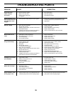
Check adjustment on right side of trac tor. Position any blade
so the tip is pointing straight forward. Measure distance "B"
at front and rear tip of the blade.
• Before making any necessary ad just ments, check that
both front plate links are equal in length.
• If links are not equal in length, adjust one link to same
length as other link.
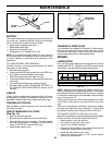
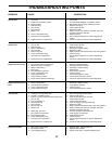
TO LEVEL MOWER HOUSING
Adjust the mower while tractor is parked on level ground
or driveway. Make sure tires are properly infl ated (See
“PROD UCT SPECIFICATIONS” section of this manual). If
tires are over or underinfl ated, you will not properly adjust
your mower.
SIDE-TO-SIDE ADJUSTMENT (See Figs. 19 and 20)
• Raise mower to its highest position.
• Measure height from bottom edge of mower to ground
level at front cor ners of mower. Distance “A” on both
sides of mower should be the same.
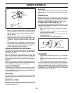
• If adjustment is necessary, make adjustment on one
side of mower only.
• To raise one side of mower, tighten lift link ad just ment
nut on that side.
• To lower one side of mower, loosen lift link ad just ment
nut on that side.
NOTE: Each full turn of adjustment nut will change mower
height about 3/16".
• Recheck measurements after ad just ing.
BOTTOM
EDGE OF
MOWER
TO GROUND
• To lower front of blade, loosen nut “C” on both front
links an equal number of turns.
NOTE: Each full turn of nut “C” will change distance. “B”
by approximately 3/16".
• When distance “B” is 1/8" to 1/2" lower at front than rear,
tighten nut “D” against trunnion on both front links.
• To raise front of blade, loosen nut “D” from trunnion on
both front links. Tighten nut “C” on both front links an
equal number of turns. The two front links must remain
equal in length.
• When distance “B” is 1/8" to 1/2" lower at front than rear,
tighten nut “D” against trunnion on both front links.
• Recheck side-to-side adjustment.
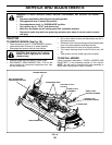
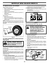
TO REPLACE MOWER DRIVE BELT
(See Fig. 23)
MOWER DRIVE BELT REMOVAL
• Park tractor on a level surface. En gage parking
brake.
• Lower attachment lift lever to its lowest position.
• Disengage belt tension rod from lock bracket.
CAUTION: Belt tension rod is spring
loaded. Have a fi rm grip on rod and
release slowly.
• Remove screws from R.H. and L.H. mandrel covers
and remove covers.
• Remove any dirt or grass clippings which may have
accumulated around mandrels and entire upper deck
surface.