


22
SERVICE AND ADJUSTMENTS
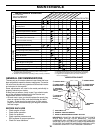
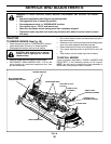
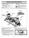
FIG. 23
027
9
0
R.H. MANDREL
COVER
R.H.
MANDREL
IDLER
PULLEYS
ELECTRIC
CLUTCH
PULLEY
• Remove belt from electric clutch pulley, both mandrel
pulleys and all idler pulleys.
MOWER DRIVE BELT INSTALLATION
• Install belt around both mandrel pulleys and around
idler pulleys as shown.
• Install belt onto electric clutch pulley.
IMPORTANT: CHECK BELT FOR PROPER ROUTING IN ALL
MOWER PULLEY GROOVES.
BELT TENSION
ROD (DISENGAGED
POSITION)
L.H. MANDREL
COVER
LOCKING BRACKET
BELT ROUTING
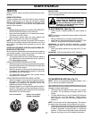
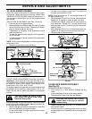
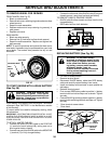
TO ADJUST ATTACHMENT CLUTCH
(See Fig. 24)
The electric clutch should provide years of service. The
clutch has a built-in brake that stops the pulley within 5
seconds. Eventually, the internal brake will wear which
may cause the mower blades to not engage, or, to not stop
as required. Adjustments should be made by your near est
authorized service center/department.
• Make sure attachment clutch and ignition switches are
in “OFF” position.
• Adjust the three nylon locknuts until space between
clutch plate and rotor measures .012" at all three slot
locations cut in side of brake plate.
NYLON
LOCKNUT (3)
FIG. 24
00751
ROTOR
CLUTCH PLATE
.012"
SLOT (3)
BRAKE PLATE
• Reassemble R.H. and L.H. mandrel covers. Securely
tighten all screws.
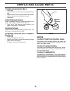
• Engage belt tension rod on locking bracket.
CAUTION: Belt tension rod is spring
loaded. Have a tight grip on rod and
engage slowly.
• Raise attachment lift lever to highest position.
NOTE: After installing a new electric clutch, run tractor at
full throttle and engage and disengage electric clutch 10
cycles to wear in clutch plate.