


8
ASSEMBLY
02306
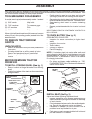
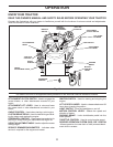
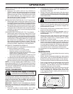
HOOK
BACKPLATE
SLOT
DISCHARGE
CHUTE
Fig. 6
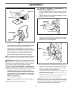
Fig. 7
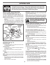
CLEVIS PIN 3/8 X 11/16
CLEVIS PIN 3/8 X 2
SUPPORT BRACKET
13/32 FLAT WASHER
RETAINER SPRING
02813
SUPPORT BRACKET
Fig. 8
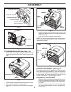
Fig. 10
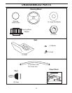
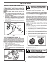
TO ASSEMBLE BAGGER (See Figs. 8-10)
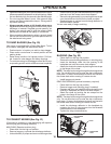
• Unfold bag by pivoting front bagger tube all the way
forward and pressing the bottom vinyl binding onto the
tube.
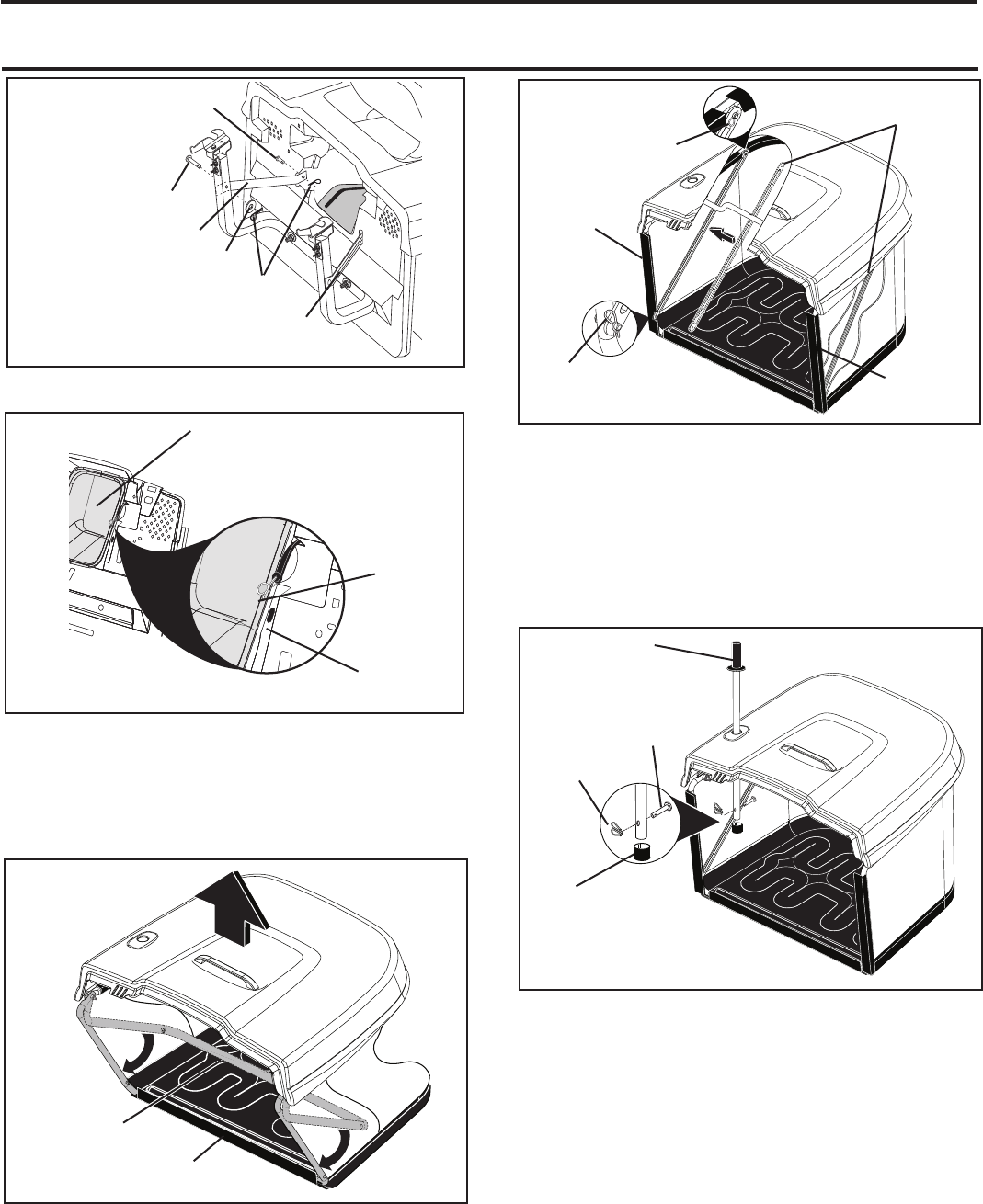
• Inside the bag, install spreader bars and retainer springs
onto pins on both sides of bag as shown.
• Press the vinyl bindings onto the sides of front bagger
tube.
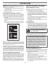
• Slide the bagger dump handle through the hole in the
bagger top, install the clevis pin 10 x 44mm and secure
with retainer clip.
• Push cap over end of bagger dump handle.
NOTE: For future use, the clevis pin may be removed in
order to use the handle to clear the chute in the event it
has become clogged.
BAGGER ADJUSTMENT (See Fig. 11)
For proper bag function and appearance, it may be nec es -
sary to adjust the bagger assembly. There should be 6mm
(1/4")-9mm (3/8") gap between the bagger top and fender
and the bagger top surface should be even with the top
surface of the fender. To adjust bagger position:
0290
5
FRONT BAGGER TUBE
VINYL
BINDING
Fig. 9
0
2906
SPREADER BARS
(Inside of bag)
RE TAIN ER
SPRING
VINYL
BINDING
VINYL
BINDING
RE TAIN ER
SPRING
02907
CLEVIS PIN
3/8 X 1-3/4
RE TAIN ER
CLIP
DUMP HANDLE
TUBE
CAP
HORIZONTAL ADJUSTMENT
• Slightly loosen the nuts securing the bagger RH and LH
hor i zon tal adjustment brackets. Loosen only enough
so the brackets keep their position, but allow them to
be moved.
• Move the brackets the amount forward or back ward
you wish the bag assembly to move. Retighten the
nuts securely.