


9
ASSEMBLY
LATCH
WELD
NUT
WASHER
LOCK
WASHER
LATCH
WELD
NUT
LOCK WASHER
WASHER
SCREW
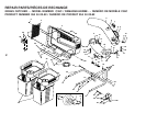
FIG. 8A
DEFLECTOR
SHIELD
FIG. 8B
LATCH
HOOKS
8
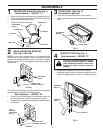
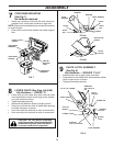
CAUTION: Do not remove discharge
guard from mower. Raise and hold guard
when attaching lower chute and allow it
to rest on chute while in operation.
LOWER CHUTE (See Figs. 8A & 8B)
Use Hardware - - GROUP "E"
• Press weld nut into rubber latch and install two latch
hook assemblies to lower chute using screw, washer,
and lock washer as shown.
• Tighten hardware securely.
• Raise and hold deflector shield in upright position.
• Place front of chute over front of mower deck opening
and slide into place, as shown.
• Hook front latch into latch bolt on front of mower deck.
• Hook rear latch into latch bolt on back of mower deck.
WA
R
N
I
N
G
ARNING
Do not operate mower unless container is properlyisnstalled.Container is
Do not operate mower unless container is properlyis
nstalled.Container is
subject to wear and detierioration. Check bag frequently
subject to wear and detierioration. Check bag frequently
. Replace when
. Replace when
cracked or damaged. Use only a recommended replacement container
cracked or damaged. Use only a recommended replacement container
.
WA
R
N
I
N
G
ARNING
D
o
n
o
t
o
p
e
r
a
t
e
m
o
w
e
r
u
n
l
e
s
s
c
o
n
t
a
i
n
e
r
i
s
p
r
o
p
e
r
l
y
i
s
n
s
t
a
l
l
e
d
.
C
o
n
t
a
i
n
e
r
i
s
Do not operate mower unles
s container
is properlyis
nstalled.Container is
s
u
b
j
e
c
t
t
o
w
e
a
r
a
n
d
d
e
t
i
e
r
i
o
r
a
t
i
o
n
.
C
h
e
c
k
b
a
g
f
r
e
q
u
e
n
t
l
y
s
ubject to wear and detierioration. Check
bag frequently
.
R
e
p
l
a
c
e
w
h
e
n
. Replace when
c
r
a
c
k
e
d
o
r
d
a
m
a
g
e
d
.
U
s
e
o
n
l
y
a
r
e
c
o
m
m
e
n
d
e
d
r
e
p
l
a
c
e
m
e
n
t
c
o
n
t
a
i
n
e
r
cracked or damaged. Use only a recommended replacement container
.
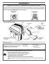
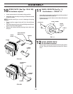
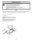
CONTAINER MOUNTING
(See Fig. 7)
No hardware required
• Install one container to left side first with warning to
outside of unit. Install other container to right side.
NOTE: Right container should always overlap left container
at center support.
• Close cover and lock latch handle over center support
tube.
7
COVER LATCH
HANDLE
CENTER
SUPPORT
TUBE
CONTAINER
WARNING
CONTAINER
HANDLE
FIG. 7
CONTAINER
WARNING
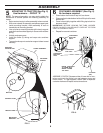
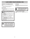
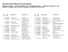
FIG. 9
UPPER CHUTE
LOCK WASHER
WELD
NUT
ACORN NUT
SPLIT
SPACER
WASHERS
3/16 X 3/4 X 16
GA.
#10 X 1-1/8" SCREW
WASHER
3/16 X 3/4 X 16 GA.
LOWER CHUTE
#10 X 5/8"
SCREW
RUBBER
LATCH
CHUTE LATCH ASSEMBLY
(See Fig. 9)
Use Hardware - - GROUPS "F & G"
• Assemble latch pin to upper chute, as shown.
• Press weld nut into rubber latch and assemble rubber
latch to lower chute, as shown.
• Tighten all hardware securely.
9