


17
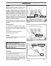
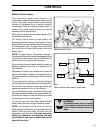
Mower Deck Leveling
Position machine on a flat surface. Preferably level
concrete.
Check the tire pressure in all four tires. Inflation
should be 15 psi.
Place 2x4’s on edge under the cutting deck from
front to rear and lower the deck down onto 2x4’s.
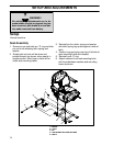
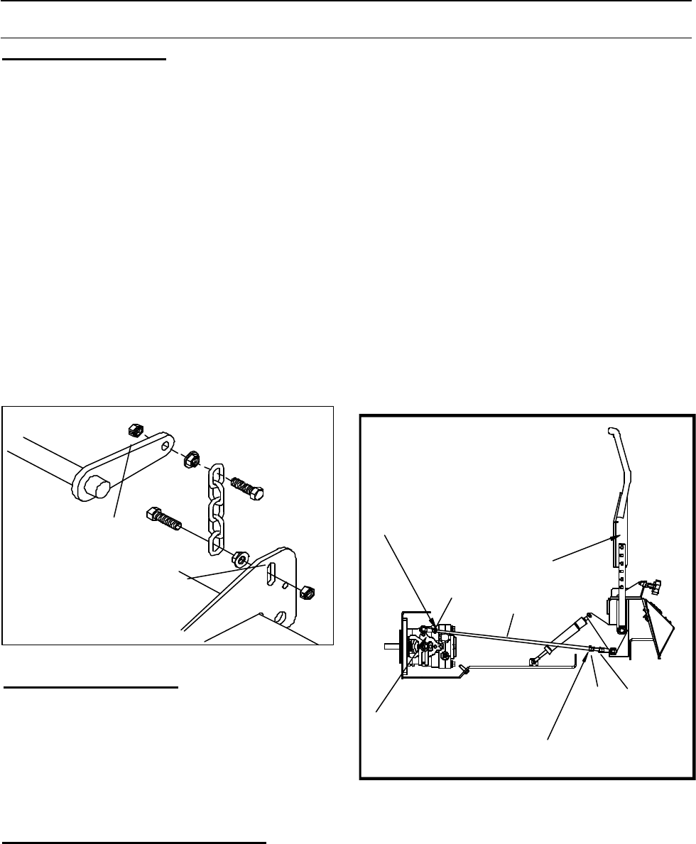
Adjust the four lower chain bolts to the center slots
on the deck. FIG - 4 NOTE: Make sure the lift
blocks under the frame are tightly bolted to the
frame.
Check the chains for equal tension. If unequal
adjust lower chain bolt in slot.
Place the deck in the 6” cutting height and mea-
sure from the cutting edge of the blade to the flat
level surface to check the deck cutting height.
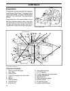
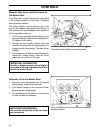
Deck Lift Arm
Slots For Chain
Adjustment
FIG - 4
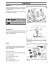
Stop engine and remove key.
Throttle lever tension may be adjusted by tighten-
ing the pivot bolt. The pivot bolt secures the throttle
arm to the mounting bracket which is mounted to
the console. Access is gained by removing the
console.
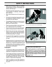
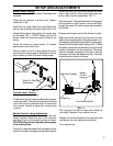
Motion Control Linkage Adjustment
This adjustment must be made with the rear
wheels rotating. Raise the rear of the machine
and block it up so the wheels are free to rotate.
CAUTION: Keep hands, feet and clothing away
from rotating tires.
Throttle Lever Tension
Place a 2x4 board between the foot plate and the
center of the seat to engage the seat safety switch.
Run engine full throttle to make sure wheels do
not rotate. Readjust if any rotation occurs.
Repeat the whole process for the opposite side
and tighten the nuts against the ball joints.
Turn machine off.
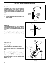
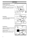
Loosen the nuts (A & B) directly behind each ball
joint on both rods (C) that connect the pump arm
to the motion control assemblies. FIG - 5
Start the engine. The park brake must be engaged
and the motion control levers in the neutral slots
to start the engine. Run the engine approximately
half throttle
Release park brake to allow the wheels to rotate.
FIG - 5
Begin with either side and put the motion control
lever into the neutral position. Adjust the motion con-
trol linkage by rotating the double nuts(D) in the proper
direction until the wheel stops rotating. FIG - 5 Move
the motion control lever forward then into the neutral
position and place it into the neutral slot. The wheel
must be stopped completely at this point. Now do
the same in reverse and release the lever. The lever
should return to neutral on its own.
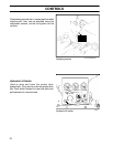
SETUP AND ADJUSTMENTS
Left Hand Threads
Motion
Control
Lever
Turn Here to Adjust
Pump Arm
B
C
A
D