


3
ADJUSTMENTS FORADJUSTMENTS FOR
ADJUSTMENTS FORADJUSTMENTS FOR
ADJUSTMENTS FOR
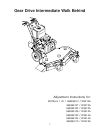
HUSQVARNA 32", 36" AND 48" COMMERCIAL MOWERSHUSQVARNA 32", 36" AND 48" COMMERCIAL MOWERS
HUSQVARNA 32", 36" AND 48" COMMERCIAL MOWERSHUSQVARNA 32", 36" AND 48" COMMERCIAL MOWERS
HUSQVARNA 32", 36" AND 48" COMMERCIAL MOWERS
AXLE HEIGHT ADJUSTMENTAXLE HEIGHT ADJUSTMENT
AXLE HEIGHT ADJUSTMENTAXLE HEIGHT ADJUSTMENT
AXLE HEIGHT ADJUSTMENT
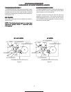
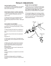
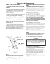
1. To adjust rear axle, stop engine and place drive levers
in the neutral lock position, remove spark plug wire.
2. Remove lower belt shield from underside of rear deck
for better access to axle adjustment bolts.
3. Loosen axle pivot bolts and axle adjustment bolts.
See figure # 1.
4. Place a jack under center of rear deck raise the jack
slightly so axle adjustment bolts may be removed.
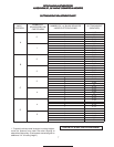
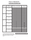
5. With the jack raise or lower the rear deck to the desired
position using the chart to ensure proper height. Reinstall
the axle adjustment bolts and tighten.
A tapered punch may be used to help align the holes.
See figure #1.
NOTE:
It may be necessary to readjust drive and brake linkages.
NOTE:
To achieve the best quality cut, the blades should be
level with the ground or slightly tipped forward
BRAKE / TRACTION ADJUSMENTBRAKE / TRACTION ADJUSMENT
BRAKE / TRACTION ADJUSMENTBRAKE / TRACTION ADJUSMENT
BRAKE / TRACTION ADJUSMENT
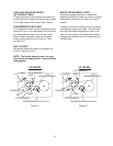
1. Disconnect the brake linkage from the brake band
arm.
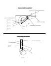
2. With the mower in gear, place the traction levers in the
drive position. Firmly pull back on the handles until the
tires slide to seat the wheel drive belts into the pulleys.
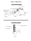
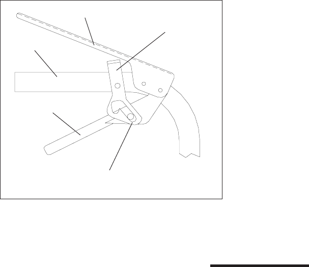
3. Measure the clearance between the bottom of the
traction lever rod and the bottom of the thumb latch slot.
It should be between 3/16" to 1/4", but not exceeding 1/
4". See Figure # 3
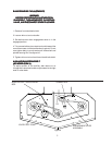
HANDLE
TRACTION LEVER
THUMB LATCH
3/16" to 1/4" CLEARANCE
O.P. LEVER
Figure 3
OPERATOR PRESENCE SWITCH ADJUSTMENTOPERATOR PRESENCE SWITCH ADJUSTMENT
OPERATOR PRESENCE SWITCH ADJUSTMENTOPERATOR PRESENCE SWITCH ADJUSTMENT
OPERATOR PRESENCE SWITCH ADJUSTMENT
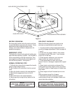
The operator presence switches can be adjusted by
loosening the screws on the side of the O.P. lever
linkage and sliding the switch up or down. The O.P.
switch should have a 1/32" to 1/16" gap between the
plunger and the bottom side of the control panel when
operator presence levers are released.
BLADE SWITCH ADJUSTMENTBLADE SWITCH ADJUSTMENT
BLADE SWITCH ADJUSTMENTBLADE SWITCH ADJUSTMENT
BLADE SWITCH ADJUSTMENT
The blade engagement switch can be adjusted by
loosening the screws on the flange under the control
panel and moving the switch in or out. The blade switch
should be adjusted so the plunger is fully depressed
when the engagement lever is fully disengaged.
ADJUSTMENTS - DRIVE BELTSADJUSTMENTS - DRIVE BELTS
ADJUSTMENTS - DRIVE BELTSADJUSTMENTS - DRIVE BELTS
ADJUSTMENTS - DRIVE BELTS
For all drive belts, tension should be set so that belt
vibration is minimized or eliminated when belts are
moving during normal operation. A properly tensioned
belt should have 1/4" to 3/8" deflection at the center of
belt span between pulleys when blades are engaged.
Blade drive belt tension is preset at the factory.
NOTE:NOTE:
NOTE:NOTE:
NOTE:
DO NOT over tighten belt. Excessive tension will
decrease belt and spindle bearing life.
4. If the clearance is less than 3/16", disconnect the
traction rod from the traction lever by removing the
hairpin cotter.
5. Adjust the traction rod to the proper clearance by
screwing it out of the swivel if clearance is less than 3 /
16".
NOTE:NOTE:
NOTE:NOTE:
NOTE:
More or less brake pressure may be desired depending
on the operator or conditions of operation. To increase
pressure tighten the wing nut on the brake linkage.