


18
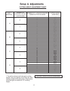
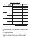
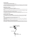
CUTTING HEIGHT ADJUSTMENT CHART
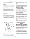
Note: To quickly achieve small changes in cutting
heights, move the spacers from under the cutter housing
to above the cutter pulley. (Each spacer moved will give
an additional 1/4" of cutting height ).
USE ONLY 4 BLADE SPACERS MAXIMUM
AXLE
POSITION
NUMBER OF
SPACERS BELOW
CASTER ARM
NUMBER OF 1/4" BLADE SPACERS
UNDER CUTTER HOUSING
CUTTING HEIGHT
(IN INCHES)
1 1/2
1 3/4
2
2 1/4
2 1/2
2
2 1/4
2 1/2
2 3/4
3
2 1/2
2 3/4
3
3 1/4
3 1/2
3
3 1/4
3 1/2
3 3/4
4
3 1/2
3 3/4
4
4 1/4
4 1/2
4
4 1/4
4 1/2
4 3/4
5
4
3
2
1
0
4
3
2
1
0
4
3
2
1
0
4
3
2
1
0
4
3
2
1
0
4
3
2
1
0
0
1
2
3
4
5
B
A
C
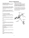
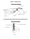
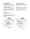
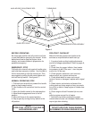
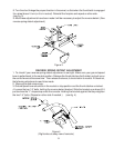
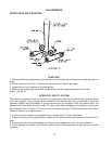
MOTION CONTROL ADJUSTMENT
1. This adjustment must be made with the drive wheels rotating. Raise rear of the unit and block it
up so the wheels are free to rotate. CAUTION: Keep hands, feet and clothing away from rotating
tires.
2. It will be necessary to make this adjustment with the reverse detents disconnected.
3. With the ground speed lever in neutral or stop position, start the engine.
4. The thumb latches should be unlocked.
5. Turn the adjusting nut the proper direction until the wheel stops rotating. This is your neutral
position, repeat on other side. (see fig. 3)
6. After the neutral position is adjusted. You will need to readjust the short linkage. (see fig. 3)
7. Remove the two hairpins, swing the linkage out of the control lever and the thumb latch.
(see fig.3)