


6
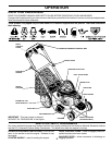
HOW TO USE YOUR LAWN MOWER
ENGINE SPEED
The engine speed was set at the factory for optimum per-
formance. Speed is not adjustable.
ENGINE ZONE CONTROL
CAUTION: Federal regulations require
an engine control to be installed on this
lawn mower in order to minimize the risk
of blade contact injury. Do not un der
any cir cumstances attempt to defeat
the function of the operator control. The
blade turns when the engine is running.
• Your lawn mower is equipped with an operator pres-
ence control bar which requires the operator to be
positioned behind the lawn mower handle to start and
operate the lawn mower.
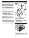
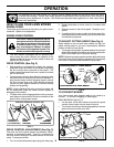
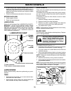
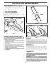
DRIVE CONTROL (See Fig. 3)
• Self-propelling is controlled by hold ing the operator
presence control bar down to the handle and pulling
the drive control lever rearward to the handle. The
farther toward the handle the lever is pulled, the faster
the unit will travel.
• Forward motion will stop when either the operator pres-
ence control bar or drive control lever are released. To
stop forward motion without stop ping engine, re lease
the drive control lever only. Hold op erator presence
control bar down against handle to con tinue mowing
without self-propelling.
NOTE: If after releasing the drive control the mower will
not roll backwards, push the mower forward slightly to
disengage drive wheels.
• To keep drive control engaged when turning corners,
push down on the handle to lift the front wheels off the
ground while turning lawn mower.
The operation of any lawn mower can result in foreign objects thrown into the eyes, which can result
in severe eye damage. Always wear safety glasses or eye shields while operating your lawn mower or
performing any adjustments or repairs. We recommend standard safety glasses or a wide vision safety
mask over spectacles.
OPERATION
TO CONVERT MOWER
Your lawn mower was shipped ready to be used as a
mulcher. To convert to bagging or discharging:
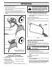
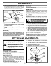
REAR BAGGING (See Fig. 5)
• Lift rear door of the lawn mower and place the grass
catcher frame hooks onto the door pivot pins.
• To convert to mulching or dis charging operation, remove
grass catch er and close rear door.
FIG. 5
PIVOT PINS REAR
DOOR
GRASS
CATCHER
HANDLE
CATCH ER FRAME HOOK
DRIVE CONTROL ADJUSTMENT (See Fig. 3)
Over time, the drive control system may become “loose”,
resulting in decreased speed. There is a turnbuckle on
the drive control housing to increase tension on the drive
cable. Pro ceed as follows:
1. Turn unit off and disconnect spark plug wire from plug.
2. Rotate turnbuckle on drive control to increase drive
speed.
3. Operate mower to test drive speed. Readjust as re-
quired.
4. If condition fails to improve after the above steps (for-
ward speed remains the same), your drive belt is worn
and should be re placed.
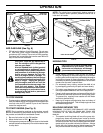
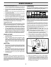
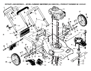
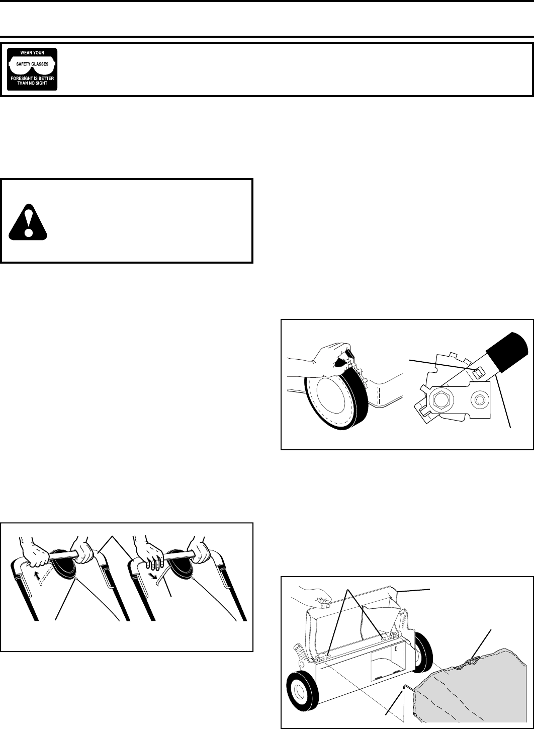
TO ADJUST CUTTING HEIGHT (See Fig. 4)
Raise wheels for low cut and lower wheels for high cut,
adjust cutting height to suit your requirements. Me dium
position is best for most lawns.
• To change cutting height, squeeze adjuster lever to ward
wheel. Move wheel up or down to suit your re quirements.
Be sure all wheels are in the same setting.
NOTE:Adjuster is properly positioned when plate tab inserts
into hole in lever. Also, 9-position adjusters (if so equipped)
allow lever to be positioned between the plate tabs.
FIG. 4
LEVER BACKWARD TO LOWER MOWER
LEVER FORWARD TO RAISE MOWER
PLATE
TAB
LEVER
TO
ENGAGE
DRIVE
CONTROL
DRIVE
CONTROL
LEVER
DRIVE
CONTROL
DISENGAGED
OPERATOR PRESENCE CONTROL BAR
FIG. 3
ADJUSTMENT
TURNBUCKLE
(ON UNDERSIDE)