


13
ENGINE
Maintenance, re pair, or re placement of the emission con-
trol de vices and sys tems, which are be ing done at the
customers expense, may be performed by any non-road
engine repair es tablishment or individual. Warranty repairs
must be performed by an authorized engine man ufacturer's
service outlet.
ENGINE SPEED
Your engine speed has been factory set. Do not attempt to
increase engine speed or it may result in personal injury. If
you believe that the engine is running too fast or too slow,
take your lawn mower to an authorized service center for
repair and adjustment.
CARBURETOR
Your carburetor is not adjustable. If your engine does not
operate properly due to suspected carburetor problems,
take your lawn mower to an authorized service center for
repair and/or adjustment.
IMPORTANT: NEVER TAMPER WITH THE ENGINE GOVERNOR,
WHICH IS FACTORY SET FOR PROPER ENGINE SPEED.
OVERSPEEDING THE ENGINE ABOVE THE FACTORY HIGH
SPEED SETTING CAN BE DANGEROUS. IF YOU THINK THE
ENGINE-GOVERNED HIGH SPEED NEEDS ADJUSTING,
CONTACT YOUR NEAREST AUTHORIZED SER VICE CEN TER,
WHICH HAS PROPER EQUIP MENT AND EXPERIENCE TO
MAKE ANY NEC ESSARY ADJUSTMENTS.
SERVICE AND ADJUSTMENTS
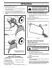
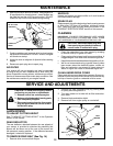
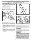
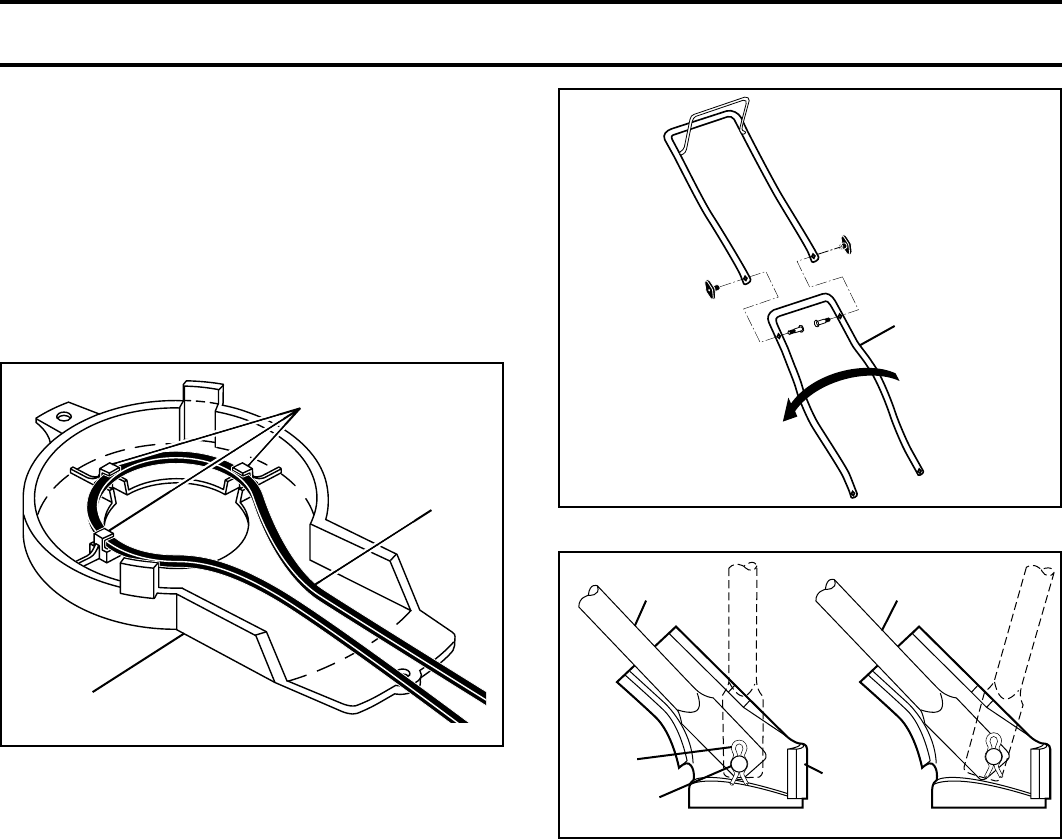
TO REPLACE DRIVE BELT (See Fig. 15)
1. Place new drive belt in belt retainers of debris shield.
2. Route the other end of the new drive belt through hole
in housing.
3. Reinstall debris shield and blade.
4. Return mower to upright po sition.
5. Install new belt on gearcase pulley.
6. Reinstall belt keeper and drive cover.
NOTE: Always use factory approved belt to assure proper
fi t and long life.
FIG. 15
DRIVE
BELT
BELT RETAINERS
DEBRIS
SHIELD
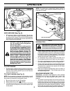
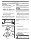
TO ADJUST HANDLE (See Figs. 16 and 17)
The handle can be mounted in a high or low position. The
mounting holes in the bottom of lower handle are off center
for raising or lowering the handle.
1. Remove upper handle and all wire tie(s) securing
cable(s) to lower handle.
2. Remove hairpin cotters from lower handle bracket
mounting pin.
3. Squeeze lower handle in to remove it from mounting pins.
4. Turn lower handle over to raise or lower handle.
5. Squeeze lower handle in and po sition holes onto
mounting pins on handle bracket.
6. Reassemble upper handle and all parts removed from
lower handle.
LOWER
HANDLE
ROTATE
FIG. 16
MOWING
POSITION
MOWING
POSITION
HIGH POSITIONLOW POSITION
HANDLE
BRACKET
MOUNTING
PIN
HAIRPIN
COTTER
FIG. 17