


GB - 10
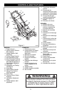
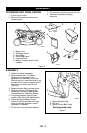
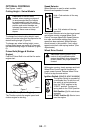
CONTROLS AND FEATURES
See Figures 1 and 6 for Controls and
Features.
Engine/Blade Control
The Engine Control must be
held against the handlebar in
order to start the engine as
well as during mowing
operations to keep the engine
running.
Releasing the control during operation stops
the engine and blade.
Handlebar
Handlebar adjusts to four positions by
selecting holes in braces. Select a safe,
comfortable height and place pin through hole
in brace that is closest to that height. Refer to
Adjustment Section for instructions.
Recoil Starter Handle
When pulled, handle will turn engine over.
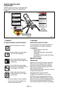
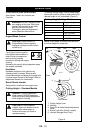
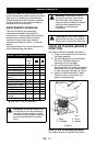
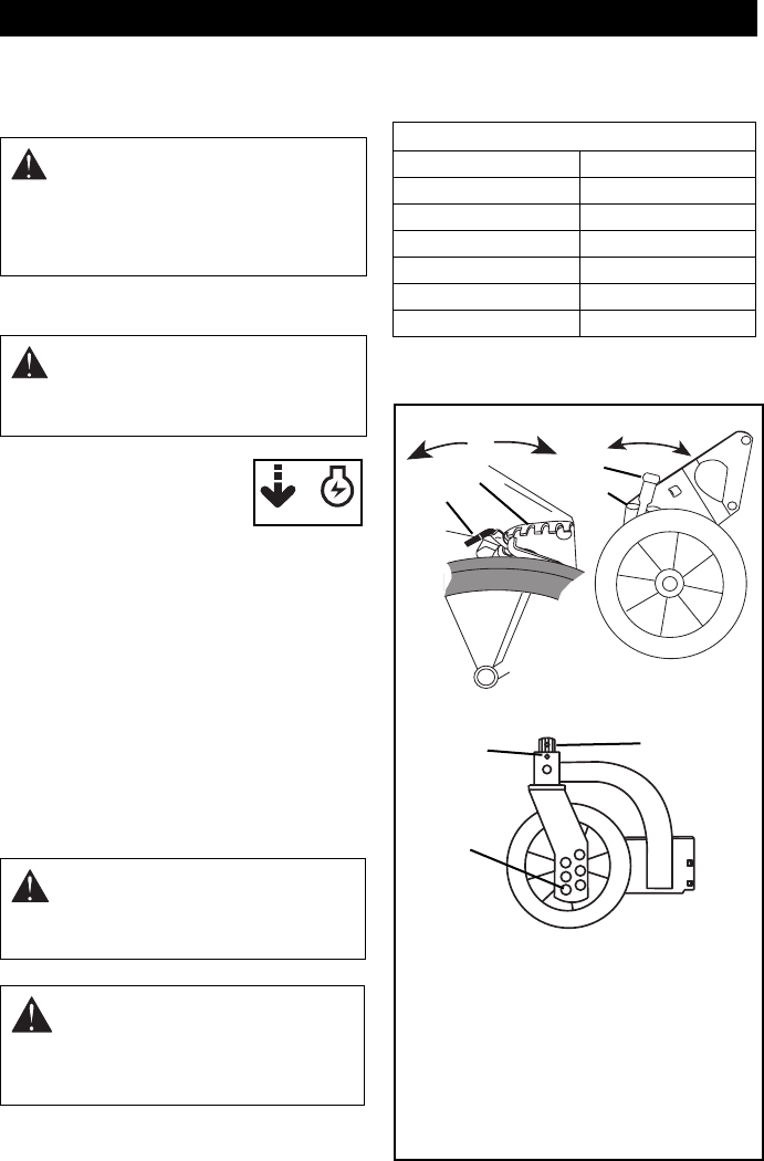
Cutting Height – Standard Models
To change cutting height, move cutting height
levers one notch at a time on each wheel until
desired height of cut is obtained. (Figure 6)
NOTE:
Each wheel on mower must be set at
the same height for a level cut.
OPERATION
WARNING:
DO NOT attempt to start
your engine at this time. Familiarize
yourself with controls to see what
they do and how they work.
Thoroughly read and understand
entire Operators Manual first.
CAUTION:
Check function of
Engine/Blade Control regularly.
Improper function of control could
cause injury.
DANGER:
To avoid inadvertent
blade contact, NEVER attempt to
make any cutting height adjustment
while engine is running.
CAUTION:
On self-propelled
models, both rear wheels must be
positioned at same height or
traction drive may not clutch or
operate properly.
OM0450
Cutting Height Settings Chart
Notch Cut grass length
LOW 1" (25 mm)
2 1-3/8" (35 mm)
3 1-3/4" (45 mm)
4 2-1/4" (57 mm)
5 2-3/4" (70 mm)
HIGH 3-1/4" (83 mm)
Low
High
Low
High
Front
Rear
1
2
3
4
5
1
2
OM0190
OM0160
OM0180
1. Cutting Height Lever
2. Notches
3. Clevis Pin & Swivel Height Adjustment
Holes
4. Swivel Lock Hole (Swivel Locked)
5. Linchpin Storage Hole (Free)
Front Swivel
Figure 6