


7
OPERATION
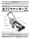
HOW TO USE YOUR LAWN MOWER
ENGINE SPEED
The engine speed was set at the factory for optimum per-
formance. Speed is not adjustable.
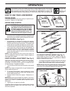
ENGINE ZONE CONTROL
CAUTION: Federal regulations require
an engine control to be installed on this
lawn mower in order to minimize the risk
of blade contact injury. Do not un der
any cir cum stanc es attempt to defeat
the function of the operator control. The
blade turns when the engine is running.
• Your lawn mower is equipped with an operator presence
control bar which requires the operator to be positioned
behind the mower handle to start and operate the mower.
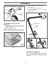
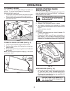
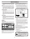
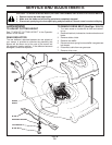
DRIVE CONTROL (See Fig. 5)
• Self-propelling is controlled by hold ing the operator
presence control bar down to the handle and pulling
the drive control bar up to the handle. The closer to the
handle the bar is pulled, the faster the unit will travel.
• Forward motion will stop when either the operator pres-
ence control bar or drive control bar are released. To
stop forward motion without stop ping engine, re lease
the drive control bar only. Hold op er a tor presence
control bar down against handle to con tin ue mowing
without self-propelling.
NOTE: If after releasing the drive control the mower will
not roll backwards, push the mower forward slightly to
disengage drive wheels.
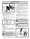
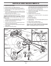
DRIVE CONTROL ADJUSTMENT (See Fig. 6)
Over time, the drive control system may become “loose”,
resulting in decreased speed. There is an adjustment
turnbuckle on the drive control cable to increase tension
on the drive belt. Pro ceed as follows:
1. Turn unit off and disconnect spark plug wire from spark
plug.
NOTE: Your mower is shipped with no “gap” between drive
control cable and jam nut.
2. To increase drive speed, rotate turnbuckle on drive
control cable until there is a small “gap” between drive
control cable and jam nut.
3. Operate mower to test drive speed. Readjust as re-
quired.
IMPORTANT: OVER-ADJUSTMENT WILL MAKE IT DIFFICULT
TO LIFT CONTROL BAR TO HANDLE AND WILL CAUSE YOUR
MOWER TO "CREEP" FORWARD WHEN CONTROL BAR IS
RELEASED.
4. Tighten jam nut against turnbuckle.
If condition fails to improve after the above steps (forward
speed remains the same), your drive belt is worn and
should be re placed.
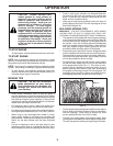
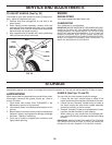
TO ADJUST CUTTING HEIGHT (See Fig. 7)
Raise wheels for low cut and lower wheels for high cut,
adjust cutting height to suit your requirements. Me di um
position is best for most lawns.
• To change cutting height, squeeze adjuster lever to ward
wheel. Move wheel up or down to suit your re quire-
ments. Be sure all wheels are in the same setting.
NOTE: Adjuster is properly positioned when plate tab inserts
into hole in lever. Also, 9-position adjusters (if so equipped)
allow lever to be positioned between the plate tabs.
FIG. 7
LEVER
ROTATE LEVER TOWARD ENGINE
TO LOWER MOWER
ROTATE LEVER AWAY FROM ENGINE TO RAISE MOWER
PLATE
TAB
FIG. 5
DRIVE CONTROL
DISENGAGED
DRIVE CONTROL
ENGAGED
DRIVE
CONTROL BAR
OPERATOR
PRESENCE
CONTROL BAR
FIG. 6
“GAP” WHILE
ADJUSTING
TURNBUCKLE
JAM NUT
“GAP” AFTER
ADJUSTMENT
ORIGINAL FACTORY
SETTING
(NO “GAP”)
DRIVE
CON TROL
CABLE
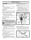
The operation of any lawn mower can result in foreign objects thrown into the eyes,
which can result in severe eye damage. Always wear safety glasses or eye shields
while operating your lawn mower or performing any adjustments or repairs. We
recommend standard safety glasses or a wide vision safety mask over spectacles.
Use ear pro-
tectors to
avoid damage
to hearing.