


ASSEMBLY
18 – English
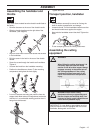
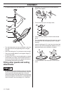
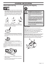
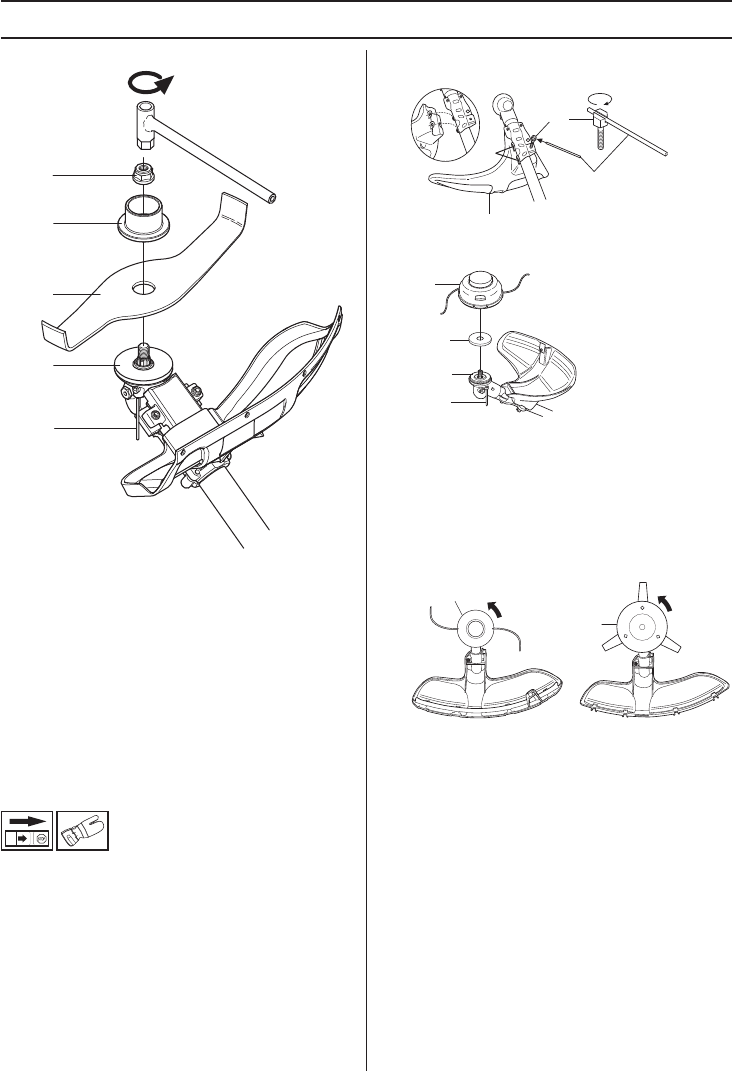
• Fit the drive disc (B) on the output shaft.
• Turn the blade shaft until one of the holes in the drive
disc aligns with the corresponding hole in the gear
housing.
• Insert the locking pin (C) in the hole to lock the shaft.
• Place the shredder blade (D) and support flange (F)
on the output shaft.
• Fit the nut (G). The nut must be tightened to a torque
of 35-50 Nm (3.5-5 kpm). Use the socket spanner in
the tool kit. Hold the shaft of the spanner as close to
the shredder blade guard as possible.
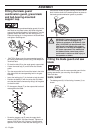
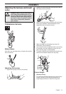
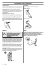
Fitting other guards and cutting
attachments
• Fit the trimmer guard/combination guard (A) intended
for use with the trimmer head/plastic blades. Hang the
trimmer guard/combination guard (A) on the two
hooks on the plate holder (M). Bend the guard around
the shaft and tighten it with the bolt (L) on the opposite
side of the shaft. Use the locking pin (C). Place the
locking pin in the groove on the screw head and
tighten. See diagram.
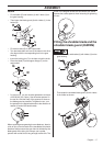
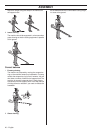
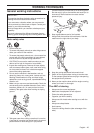
• Fit the drive disc (B) on the output shaft.
• Centre the metal cup (P) on the drive disc’s blade
guide.
• Turn the blade shaft until one of the holes in the drive
disc aligns with the corresponding hole in the gear
housing.
• Insert the locking pin (C) in the hole to lock the shaft.
• Screw on the trimmer head/plastic blades (H) in the
opposite direction to the direction of rotation.
• To dismantle, follow the instructions in the reverse
order.
B
G
F
D
C
L
A
M
C
B
H
P
C
H
H