


16 – English
ASSEMBLY
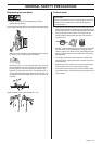
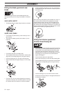
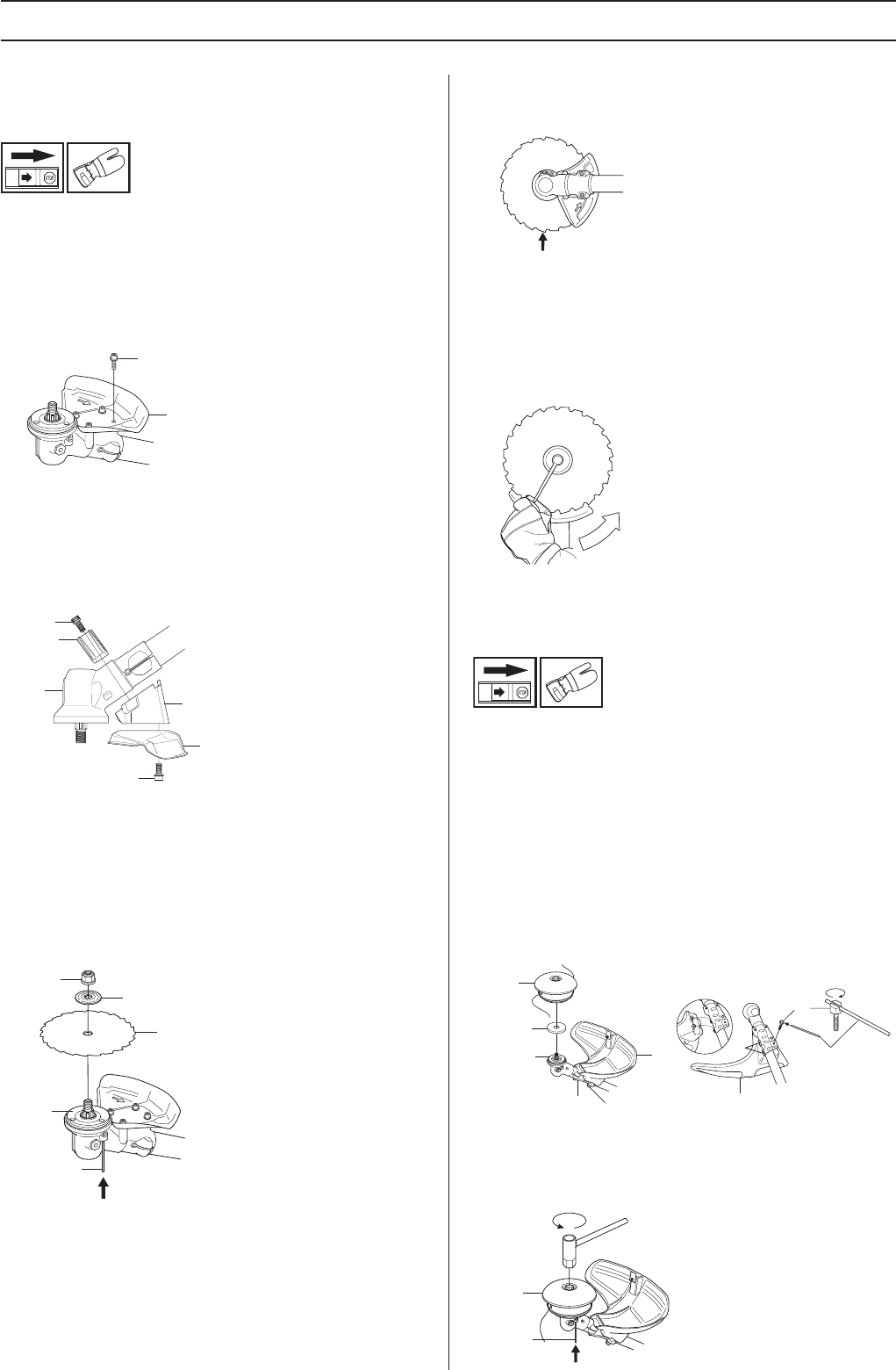
Fitting the blade guard and saw
blade
CAUTION! Always use the recommended guard for the
cutting attachment you are using. See chapter on Technical
data.
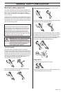
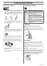
343F, 345FX, 345FXT
• The blade guard (A) is fitted using 4 screws (L) as shown.
343FR, 343R, 345RX
• Fit the holder (R) and bracket (J) with 2 bolts (H) on the
gear housing.
• Then fasten the blade guard (A) with 4 bolts (L) in the
holder (N).
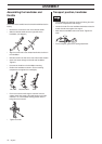
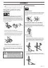
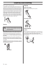
• Fit the drive disc (B) on the output shaft.
• Turn the blade shaft until one of the holes in the drive disc
aligns with the corresponding hole in the gear housing.
• Insert the locking pin (C) in the hole to lock the shaft.
• Place the blade (D) and support flange (F) on the output
shaft.
• Fit the nut (G). The nut must be tightened to a torque of
35-50 Nm (3.5-5 kpm). Use the socket spanner in the tool
kit. Hold the shaft of the spanner as close to the blade
guard as possible. To tighten the nut, turn the spanner in
the opposite direction to the direction of rotation (Caution!
left-hand thread).
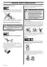
When loosening and tightening the saw blade nut, there is a
risk of injury from the teeth of the saw blade. You should
therefore always ensure that your hand is shielded by the
blade guard when doing this. Always use a socket spanner
with a shaft that is long enough to allow this. The arrow in the
diagram shows the area where you should operate the socket
spanner when loosening or tightening the nut.
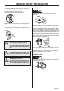
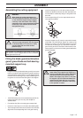
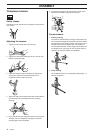
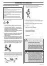
Fitting the trimmer guard and
trimmer head Trimmy SII
• Fit the correct trimmer guard (A) for use with the trimmer
head. Hang the trimmer guard/combination guard (A) on
the two hooks on the plate holder (M). Bend the guard
around the shaft and tighten it with the bolt (L) on the
opposite side of the shaft. Use the locking pin (C). Place
the locking pin in the groove on the screw head and
tighten. See diagram.
• Fit the drive disc (B) on the output shaft.
• Centre the metal cup (P) on the drive disc’s blade guide.
• Turn the blade shaft until one of the holes in the drive disc
aligns with the corresponding hole in the gear housing.
• Insert the locking pin (C) in the hole to lock the shaft.
• Screw on the trimmer head (H) in the opposite direction to
the direction of rotation.
A
L
H
J
K
L
R
A
F
G
D
B
C
B
A
M
L
H
P
L
A
M
C
H
C