


English – 15
ASSEMBLY
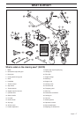
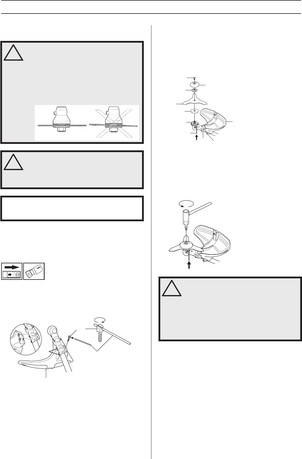
Assembling the cutting equipment
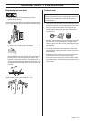
Fitting the blade guard/combination
guard, grass blade and ball-bearing-
mounted support cup
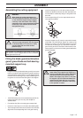
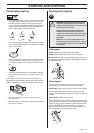
• Hang the trimmer guard/combination guard (A) on the two
hooks on the plate holder (M). Bend the guard around the
shaft and tighten it with the bolt (L) on the opposite side of
the shaft. Use the locking pin (C). Place the locking pin in
the groove on the screw head and tighten. See diagram.
• CAUTION! Always use the recommended guard for the
cutting attachment you are using. See chapter on
Technical data.
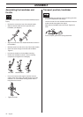
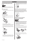
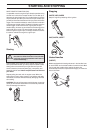
• Fit the drive disc (B) on the angle gear’s output shaft.
• Centre the metal cup (P) on the drive disc’s blade guide.
• Turn the output shaft until one of the holes in the drive disk
aligns with the corresponding hole in the gear housing.
• Insert the locking pin (C) in the hole to lock the shaft.
• Position the blade (D) with the drive disk (B). Make sure
that the blade is centered by fitting it to the guide on the
drive disk.
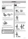
• Fit the support flange (F) on the output shaft so that it
rests against the blade.
• Screw the support cup (E) onto the output shaft threads
(CAUTION! Left-hand thread). Tighten to a torque of 35-
50 Nm (3.5-5.0 kpm). Use the socket spanner in the tool
kit. Note that the locking pin (C) must remain inside the
gear housing to lock the drive disk. Hold the shaft of the
socket spanner as close to the blade guard/combination
guard as possible.
!
WARNING!
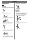
When fitting the cutting attachment it is
extremely important that the raised section
on the drive disc/support flange engages
correctly in the centre hole of the cutting
attachment. If the cutting attachment is fitted
incorrectly it can result in serious and/or
fatal personal injury.
!
WARNING! Never use a cutting attachment
without an approved guard. See the chapter
on Technical data. If an incorrect or faulty
guard is fitted this can cause serious
personal injury.
IMPORTANT! If a saw blade or grass blade are to be used
the machine must be equipped with the correct handlebar,
blade guard and harness.
L
A
M
C
!
WARNING! Tighten the lock screw (N) in the
center hole of the support cup. Tighten to a
torque of 35-50 Nm (3.5-5.0 kpm), CAUTION!
Left-hand thread. If the lock screw is not
fitted in the support cup, there is a risk that
the support cup will come unscrewed. This
means that the blade will also come loose,
which could result in serious or fatal injury
to the operator or others.
E
N
F
D
B
C
A
M
L
P