


English – 13
ASSEMBLY
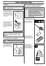
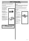
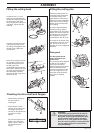
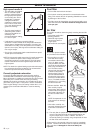
Checking the drive shaft and flanges
• Check that the threads on
the drive shaft are
undamaged.
• Check that the contact
surfaces of the cutting disc
and flanges are flat, run
correctly on the spindle and
are free from foreign
objects.
Do not use flanges that are
twisted, have damaged
edges, untrue or dirty. Do
not use different size
flanges.
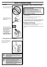
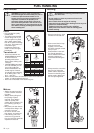
!
WARNING!
16 inch disc guards should only be used on
power cutters originally equipped with a 16"
disc guard. If a disc guard is fitted as a spare
part on a power cutter originally equipped
with a 12" or 14" disc guard, the 16" cutting
disc will rotate too quickly. A cutting disc with
too high speed can burst or cause serious
injury and damage.
4
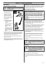
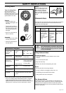
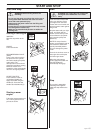
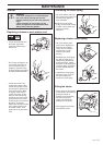
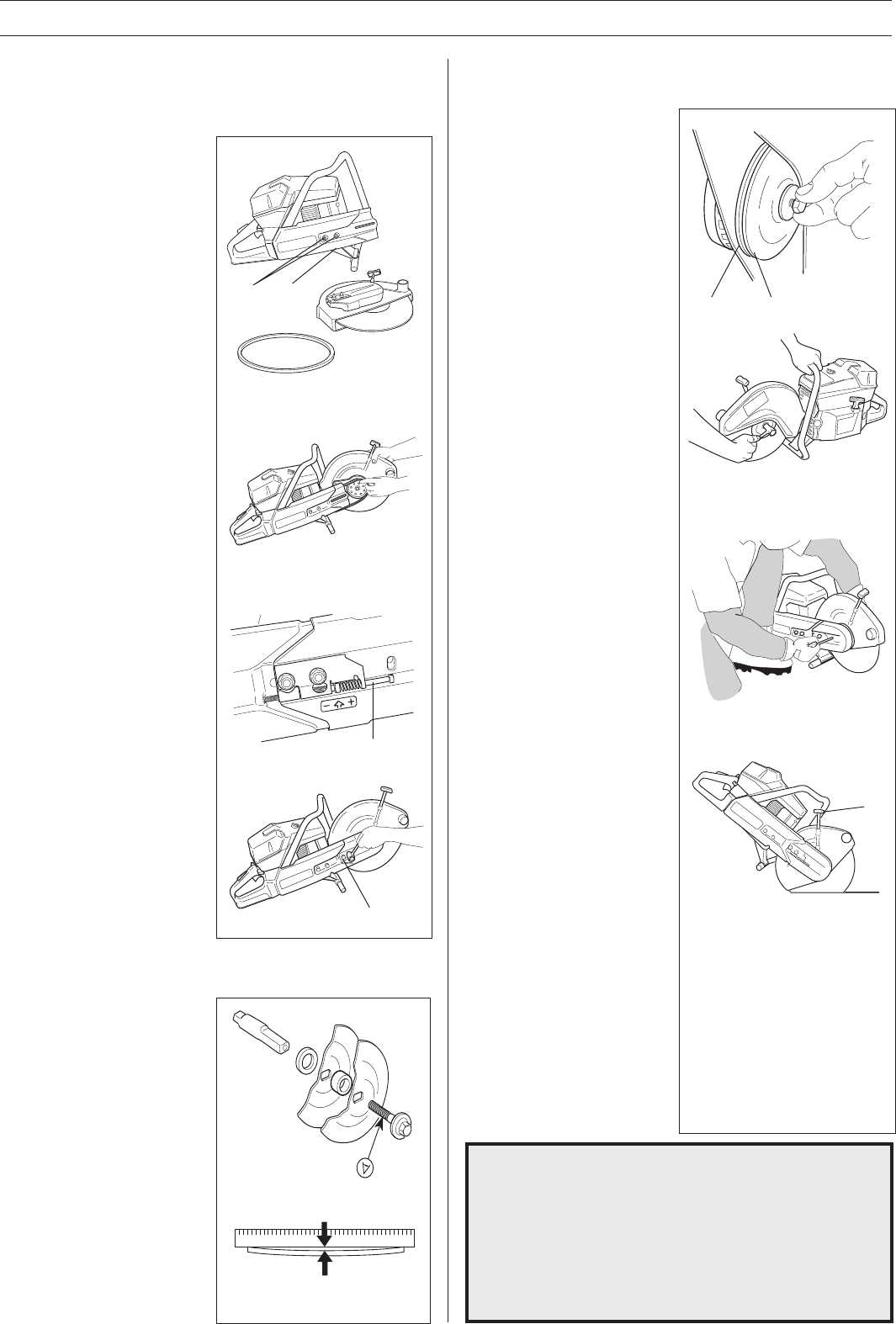
Fitting the cutting head
Undo both nuts (1) on the
cutting arm and the bolts (2).
Remove the cutting arm and fit
the drive belt on the clutch
drum. Replace the cutting arm
in position. Tighten the nuts
and bolts.
Thread the drive belt over the
cutting head’s pulley and fit
the cutting head together with
the belt guard. Tighten the
nuts by hand.
Screw in the tensioning screw
(3) so that the square nut is
located above the arrow on
the belt guard. This
automatically sets the correct
belt tension. Tighten both nuts
(4) using the socket spanner.
New drive belts should be
retensioned after using one or
two tanks of fuel.
1
2
3
A
B
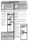
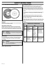
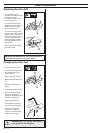
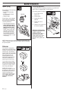
Fitting the cutting disc
Husqvarna cutting discs are
manufactured and approved
for freehand cutting. The
paper labels on each side of
the disc are there to distribute
the pressure from the flange
washer and prevent the disc
from slipping.
The disc is placed between
the flange hub (A) and the
flange washer (B). The flange
washer is turned so that it fits
in the flange hub. The cutting
disc is tightened using the
socket spanner 501 69 17-02.
The shaft can be locked using
a screwdriver, steel pin or the
like. This is slid in as far as
possible. The disc is tightened
clockwise.
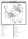
Disc guard
The disc guard should
always be fitted on the
power cutter.
The guard should be adjusted
so that the rear section is
close to the work piece.
Cutting fragments and sparks
are then collected by the
guard and led away from the
user. By using the lever (A)
the guard can be loosened
and set in the required
position.
A