


22 – English
Maintenance
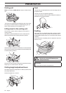
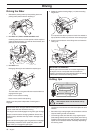
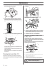
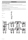
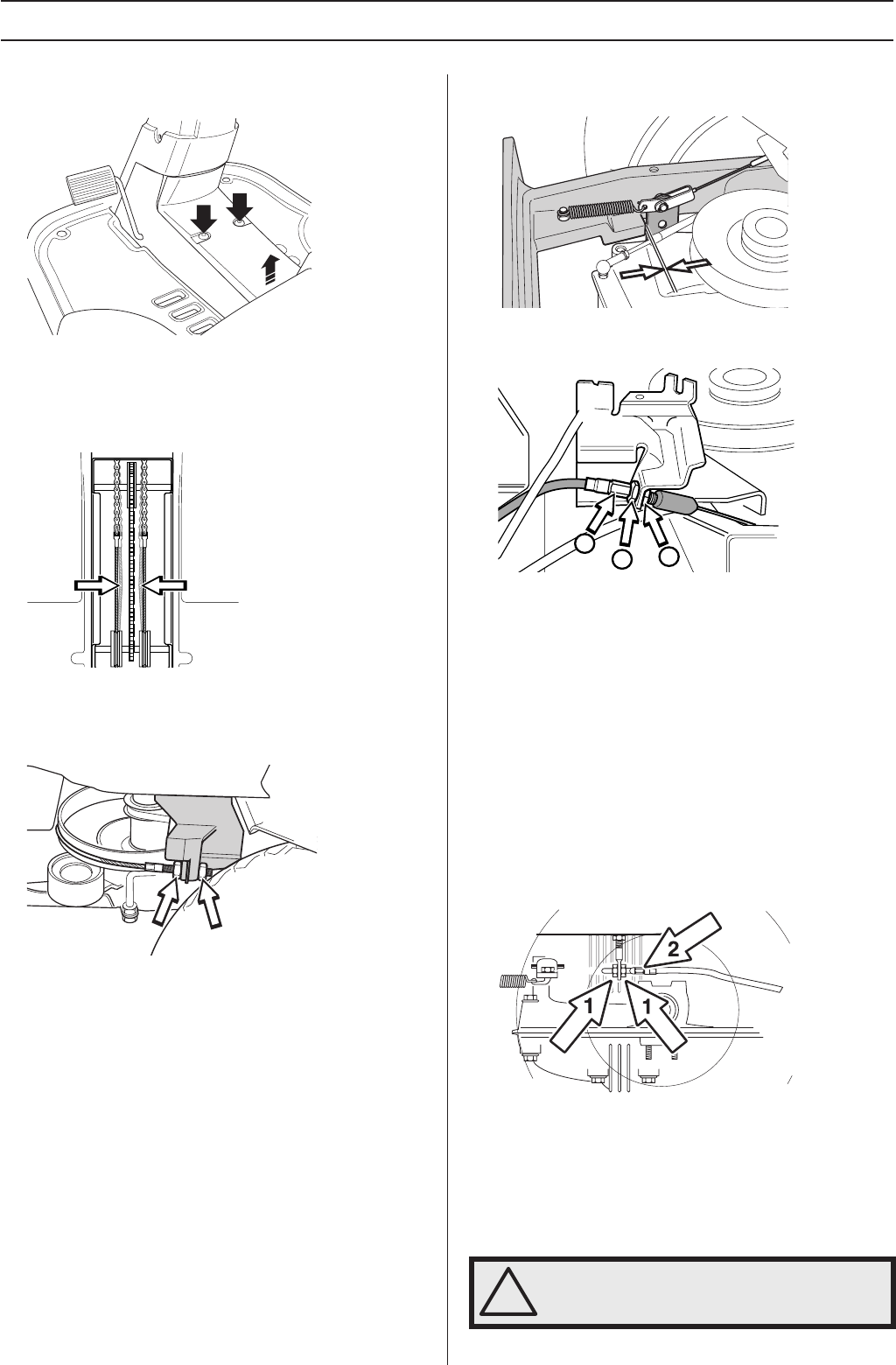
1 Remove the frame plate by loosening the screws (2) and
lift the frame plate by the rear edge.
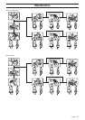
2 Check the tension of the steering wires by squeezing
them together by the arrows as illustrated. It should be
possible to push them together so that the distance
between them is half as much, without using unnecessary
force.
3 If necessary, the wires can be adjusted by tightening the
adjuster nuts on each side of the steering collar. Do not
over tighten the cables; they should only be drawn in
towards the steering collar.
Hold the cable, for example using an adjustable wrench,
so that it does not twist.
If you only tension one side the steering wheel’s centre
position may change.
Check the wire tension on completion of the adjustment
as per item 2.
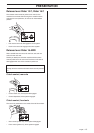
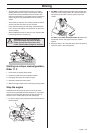
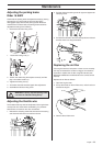
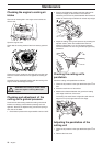
Checking the brake Rider 11 C
The brake is a disc brake and is located on the gearbox.
Check that the brake is adjusted correctly by measuring the
distance between the brake lever and front edge of the cut-out
on the chassis.
The distance should be 0-1 mm (0-0.040') when the brake is
not actuated.
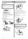
Adjusting the brake Rider 11 C
1 Loosen the locking nuts (1).
2 Tension the cable with the adjuster screw (2) so that the
distance between the brake lever and front edge of the
cut-out on the chassis is 1 mm (0.040”).
3 Tighten the locking nuts (1) after adjustment.
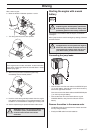
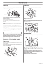
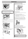
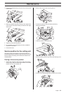
Adjusting the parking brake Rider 13
C, Rider 16 C
Check that the brake is correctly adjusted by placing the
machine on a slight downhill slope with the clutch disengaged
and activating the brake.
When the machine does not stand still, the brake should be
adjusted according to the following.
1 Loosen the locking nuts (1).
2 Tension the cable using the adjuster screw (2) until the
play in the cable is taken up.
3 Tighten the locking nuts (1).
4 The brake should be checked again after adjustment
!
WARNING! A poorly adjusted brake can
result in reduced braking ability.
2
1
1