


6
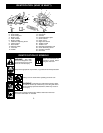
SAFETY NOTICE:
Exposure to vibrations
through prolonged use of gasoline powered
hand tools could cause blood vessel or ner ve
damage in the fingers, hands, and joints of
people prone to circulation disorders or
abnormal sw ellings. Prolonged use in cold
weather has been linked to blood vessel
damage in otherw ise healthy people. If
symptoms occur such as numbness, pain,
loss of strength, change in skincolor ortexture,
or loss of feeling in the fingers, hands, or joints,
discontinue the use of this tool and seek
medical attention. An anti-vibration system
does not guarantee the avoidance of these
problems. Users w ho operate power tools on
a continual and regular basis must monitor
closely their physical condition and the
condition of this tool.
ASSEMBLY
Protective gloves (not provided) should be
worn during assembly.
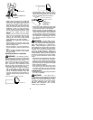
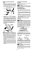
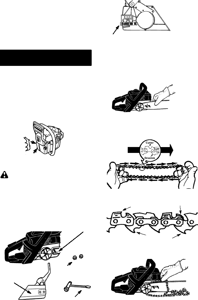
ATTACHING THE OPTIONAL
BUMPER SPIKE
The optional bumper spike may be used as a
pivot when making a cut.
S
Loosen and remove the chain brake nuts
and the chain brake from the saw.
S
Attach the bumper spike (optional) with the
two screws as illustrated.
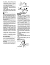
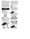
ATTACHINGTHE BAR& CHAIN
(If not
already attached)
WARNING:
If received assembled,
repeat all steps to ensure your saw is prop-
erly assembled and all fasteners are secure.
Always wear gloves when handling the
chain. The chain is sharp and can cut you
even when it is not moving!
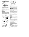
S
Loosen and remove the chain brake nuts
and the chain brake from the saw.
S
Remove the plastic shipping spacer (if
present).
Chain Brake
Chain Brake
Nuts
Bar Tool
Location of shipping spacer
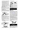
S
An adjusting pin and screw is used to adjust
the tension of the chain. It is ver y important
whenassembling thebar ,that the pin located
on the adjusting screw aligns into a hole in
the bar. T ur ning the scr ew will move the ad-
justment pin up and down the screw. Locate
this adjustment before you begin mounting
the b a r onto the saw. Se e illustra tion below.
Adjustment located on Chain Brake
Inside view of
Chain Brake
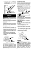
S
Tur n the adjusting screw by hand counter-
clockwise until the adjusting pin just touches
the stop. This should allow the pin to be near
the correct position. Further adjustment may
be necessary as you mount the bar.
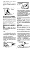
S
Slide guide bar behind clutch drum until
guide bar stops against clutch drum
sprocket.
Mount the bar
S
Prepare the chain by checking the proper di-
rection. Without following the illustration it is
easytoplacethechainonthesawinthe
wrong direc tio n. Use the illus tr a tio n o f the
chain to determine the proper direction.
CUTTERS MUST FACE IN
DIRECTION OF ROTATION
Tip of
Bar
Cutters
Depth Gaug
e
Drive Links
S
Place the chain over and behind the
clutch, fitting the drive links in the clutch
drum sprocket.
Place chain onto the sprocket