


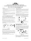
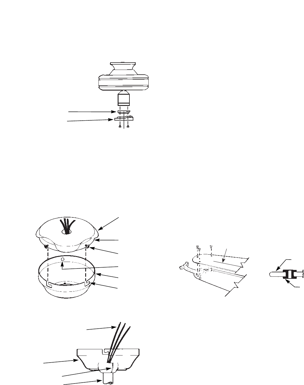
NOTE: Some Hunter fans require a special adaptor plate
between the switch housing and the light kit. This plate is pro-
vided with those fans which need it. It should be installed as
shown in Figure 5C. If the switch housing on your fan is 3-1/4"
diameter or less you do not need the adaptor, mount the light kit
directly to the switch housing.
FIGURE 5C
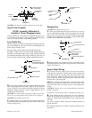
Step 7: Finish Fan Assembly
A.
The ceiling plate has (3) mounting screw holes located on
the side. Lift up the rubber cover and install (2) #10-32 X 1/2"
Phillips round head screws halfway into two of these holes. See
Figure 6.
Remove the fan from the ceiling plate hook. Make sure not to
break any wire connections. The canopy has (2) mating slots and
(1) mating hole. See Figure 6.
FIGURE 6
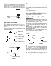
FIGURE 7
B. Position (2) slots in canopy directly under and in line with
(2) mounting screws in ceiling plate. Lift fan until ceiling plate
mounting screws are seated in bottom of slots in canopy. Rotate
fan counterclockwise until both mounting screws drop into slot
recesses. Tighten screws securely. Install third screw into mount-
ing hole.
CAUTION: Failure to securely assemble the canopy screws
could result in the fan falling.
NOTE: For the hanging fan configuration, rotate fan until
groove in ball is positioned over tab in canopy. Make certain
groove and tab are engaged before running fan. See Figure 7.
Failure to do this could result in the fan falling.
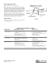
Step 8: Fan Blade Assembly, Installation,
and Balancing
NOTE: Attach each blade with the central line (ridge) facing
upward and flat side of blade facing downward. Correct installa-
tion is with the ridge upwards towards the ceiling.
A. Attach wood blades to blade brackets using three screws
for each blade. See Figure 8. If your blades have large holes
you must first insert the rubber grommets into the holes. See
Figure 8A.
NOTE: Grommets are usually assembled by hand. If you use a
tool, make certain you do not damage the grommet or blade
when inserting the grommets.
Next assemble the blade to the blade bracket. Make sure all
screws are tight to prevent vibration or wobbling.
Even when the screws are tight, the blades may seem to be
loose. This is normal when using grommets and will not be a
problem.
FIGURE 8 FIGURE 8A
B. Remove the screws and rubber bumpers from the motor
hub. Insert a mounting screw (provided) in hole in blade bracket.
Use a screwdriver to hold in place. Align blade holes with
mounting holes in hub by turning screw and readjusting blade
bracket until screw mates with threaded hole in hub. Do not
tighten until both screws have been put in blade bracket. Repeat
for all blades. See Figure 9.
C. A blade balancing kit has been provided with your fan.
Should the fan wobble in operation, you may use this kit to cor-
rect the balance per the instructions supplied with the kit.
RUBBER COVER
LIGHT KIT
ADAPTOR
LIGHT KIT
CEILING PLATE
GROMMET
BLADE
MOUNTING SCREWS
MOUNTING HOLE
MOUNTING SLOTS (2)
CANOPY
ROTATE BALL UNTIL GROOVE IN BALL
ENGAGES TAB IN CANOPY
LEAD WIRES
CANOPY
GROOVE IN BALL
PIPE NIPPLE
FORM NO. 41110-01 6/95 - 3 - ©1995 HUNTER FAN CO.
TM
RIDGE