


FIGURE 4
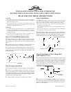
CAUTION: Use spacers only if fan is mounted to a flat ceiling.
Step 5: Fan Assembly
NOTE: Assembly Methods For
Installer’s Choice Hanging System
Your new Hunter fan can be hung in (2) different manners, one as
a low profile fan, the other as a ball type hanging fan. Read Steps
5 and 7 to decide which style of mounting you prefer.
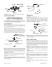
Low Profile Fan
A.
The canopy has (4) holes in the bottom. The large center hole
fits over the adaptor on top of the fan. The (3) remaining holes are
for the canopy assembly screws.
Place the canopy on top of the fan and align the proper holes.
See Figure 5. Make certain you have located the hole pattern by
checking to see that the canopy sits flat on top of the fan without a
space between the bottom of the canopy and the top of the fan. If a
space is present, rotate the canopy slightly, eliminating the space.
FIGURE 5
B. Next, poke through the neoprene material behind the holes
with a sharp object, then secure the canopy to the top of the fan
using (3) #10-32 screws with lockwashers packaged with the
adaptor kit. Make certain the screws are tight. Failure to do so
could result in the fan falling.
CAUTION: To ensure proper engagement of the canopy assem-
bly screws, the canopy must fit snug against the top of the fan.
CAUTION: Do not lift motor by wires.
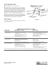
C. Being careful not to scratch the canopy finish, hang the fan
from the hook in the ceiling plate using one of the (2) slots in the
canopy. See Figure 5A.
FIGURE 5A
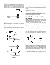
Hanging Fan
CAUTION: Do not lift motor by wires.
A. Insert pipe nipple through canopy and feed wires from top
of motor through pipe nipple. Screw pipe nipple into fan until
tight (at least 4-1/2 turns). The setscrew locking the pipe nipple
to motor must be tightened very securely. See Figure 5B. Failure
to tighten screw could result in fan falling.
FIGURE 5B
B. Being careful not to scratch the canopy finish, hang the fan
from the hook in the ceiling plate using one of the (2) slots in the
canopy. See Figure 5A.
Step 6: Final Wiring
A.
Connect electrical supply leads to the leads from motor,
using approved connectors. Connect black electrical supply lead
to the black motor lead and the black with white stripe motor
lead (see Note). Connect the white electrical supply lead to the
white motor lead. Connect the ground wire to the green leads
from the motor and ceiling plate.
NOTE: If a separate wall switch will be used to control a light-
ing accessory, connect the black wire with white stripe to the
wall switch lead. The wall switch must be a listed general-use
switch.
CAUTION: No bare wire or wire strands should be visible after
making connections.
If a light kit is used it must be marked “Suitable for outdoor use.”
B. After making the wire connections, the wires should be
spread apart with the white and green wires on one side of the
outlet box, and the black and black/white wires on the other side
of the box.
The splices should be turned upward and pushed carefully up
into the outlet box.
C. Install the light kit in accordance with the instructions sup-
plied with it.
SUPPORTING
STRUCTURE
CEILING
PLATE
GROUND
WIRE
CANOPY
CEILING PLATE
HOOK
NEOPRENE
COVER
RUBBER
SPACERS
(OPTIONAL)
MOUNTING
SCREWS
CEILING
PLATE
SCREWS WITH
LOCKWASHERS AND
LOCTITE ON THREAD
CANOPY
SCREW HEAD
SCREW HOLE
FAN ASSEMBLY
ADAPTOR
6" MIN.
MOTOR
LEAD WIRES
PIPE NIPPLE BALL
CANOPY
PIPE NIPPLE
PIPE NIPPLE
SETSCREW
(TIGHTEN SECURELY)
FORM NO. 41110-01 6/95 - 2 - ©1995 HUNTER FAN CO.
TM