


© 2003 HUNTER FAN CO. 41556-01 8/08/03
4
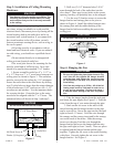
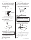
Set
Screws
Figure 5
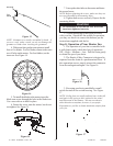
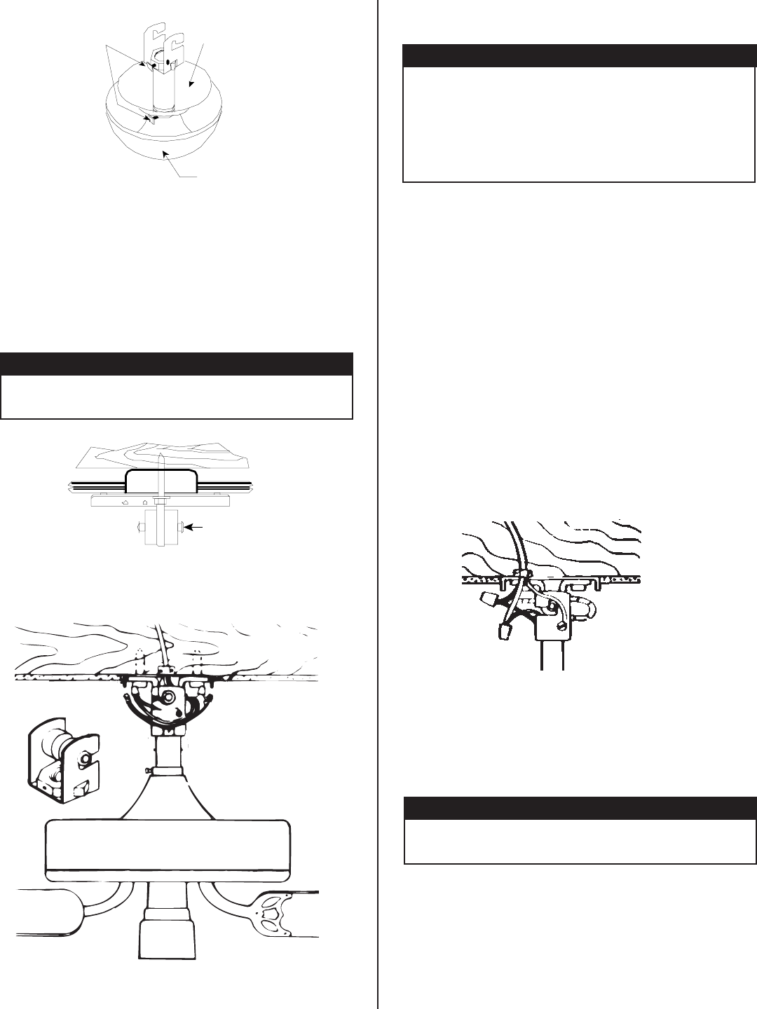
3. Be sure the pin is centered in the rubber
bushing. See Figures 6 and 7.
4. Lift the fan by the motor housing and hook
the hanger bracket onto the pin in the rubber bush-
ing. Make sure both ends of the pin are outside
the hanger bracket. See Figure 7.
Figure 6
Figure 7
Bushing Pin
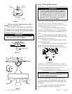
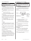
Step 5: Wiring Instructions
NOTE: Before you do the final wiring, you should decide
Figure 8
a lighting accessory, connect the black wire with the
white stripe to the wall switch lead, following the wiring
instructions included with the accessory. The wall
switch must be a listed general-use switch.
4. After making the wire connections, the wires
!
WARNING
!
• Failure to perform these steps in the correct
order may result in the fan falling.
!
WARNING
!
• To avoid possible electrical shock, before wir-
ing fan, disconnect power by turning off the cir-
cuit breakers both to the outlet box and to its
associated wall switch location. If you cannot
lock the circuit breakers in the “OFF” position,
securely fasten a prominent warning device,
such as a tag, to the service panel.
how you want to control your fan - with a pull cord, a
wall switch or a speed control. At this point, you should
also decide if you want to add a light adapter kit.
Separate wiring instructions for Hunter accessories are
included in the accessory packages.
• All wiring must be in accordance with na-
tional and local electrical codes. If you are unfamil-
iar with wiring, you should use a qualified electri-
cian.
1. Connect the black electrical supply lead to
the black motor lead and the black with white stripe
motor lead. (See Note below.)
2. Connect the white electrical supply lead to
the white motor lead.
3. Connect the ground wire to the green screw
on the side of the hanger bracket. See Figure 8.
NOTE: If a separate wall switch will be used to control
!
CAUTION
!
• No bare wires or wire strands should be vis-
ible after making connections.
should be spread apart with the white and green
wires on one side of the outlet box, and the black
and black with white stripe wires on the other side
of the box.
5. The splices should be turned upward and
pushed carefully up into the outlet box.
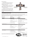
Canopy
Insert
Canopy