


T775J ELECTRONIC REMOTE TEMPERATURE CONTROLLER
63-2248—4
9
Use shielded cable if any of the above conditions cannot be
avoided.
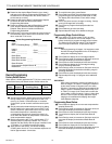
Device Setup
³ Determine the loads to be controlled and the operating
mode (heat or cool) and enter on the worksheet.
For example: Load 1: Compressor 1 (cool)
Setpt 1 _____ On at _____
Diff 1 _____ Off at _____
· Determine the setpoint (Setpt) and the switching
differential (Diff) temperatures for each on/off load and
enter on the worksheet.
For example: Load 1: Compressor 1 (cool)
Setpt 1
78°F On at 82°F
Diff 1
4°F Off at 78°F
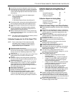
» Refer to the Control Algorithm section to calculate the
load on and off temperatures and enter on the
worksheet. Remember that on/off outputs are off at
setpoint in both the heating and cooling operating
modes. When in cooling mode, the load will be turned
on at setpoint plus the differential. When in heating
mode, the load will be turned on at setpoint minus the
differential.
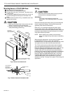
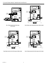
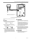
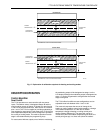
Fig. 15. Reset control with ML984 Valve Actuator.
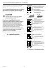
CAUTION
The T775J will not allow the user to program for both
heating and cooling loads to be energized at the same
time.
If this situation results, cooling loads will be energized
and heating loads will be prevented from also
energizing. The number (1,2) of these nonenergized
loads will flash, along with the word HEAT, to indicate
a call for both heating and cooling loads controlled by
one sensor has occurred and to alert the user to
reprogram the affected control values.
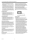
¿ To calculate the Reset Ratio to be used, determine the
number of degrees the setpoint for the control sensor A
should be reset (Reset Ratio A Value) to compensate
for a change in the reset compensation sensor B (Reset
Ratio B Value). Enter the values on the Device
Programming Worksheet (values should be whole
numbers from 1 to 30).
CAUTION
A reset ratio lower than one can result in unstable
control. Widening the throttling range and/or
differential will minimize this effect.
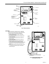
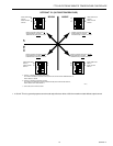
DIP SWITCHES
FOR SENSOR TO
LOAD SELECTION.
M4716
T1 T2
ML984 ACTUATOR
POWER
INPUT
1
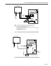
1 POWER SUPPLY. PROVIDE DISCONNECT MEANS AND
OVERLOAD PROTECTION AS REQUIRED.
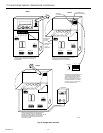
BRW
250 OHM
SELECT
SET
ENTER
NO COM NC
OUTPUT 1
OUTPUT 2
NO COMNC
120V
COM
240V
12
3
4
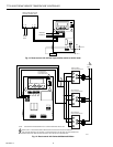
SA SB
1
23
1
2
3
4
5
678
SA TOD 24V SB
C/F
BRW