


T775J ELECTRONIC REMOTE TEMPERATURE CONTROLLER
63-2248—4
10
´ Determine the desired Reset Direction (up or down)
and enter on the Device Programming Worksheet. This
will determine if the setpoint for the control Sensor A
will be reset up or down.
² Determine the desired Reset Compensation Setpoint
for Sensor B. Enter the value on the Device
Programming Worksheet.
¶ Determine whether the desired Reset Action should
occur
above
or below the Reset Compensation
Setpoint. Enter abo
ve
or
below
on the Device
Programming Worksheet.
º Remove the T775J cover and enter the values listed on
the worksheet and the date in the first column on the
label inside the T775J cover.
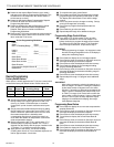
Device Programming Worksheet
Load 1:
Setpt 1 ___________ On at __________
Diff 1 or Throttling Range __ Off at __________
Load 2:
Setpt 2 ___________ On at __________
Diff 2 ____________ Off at __________
Reset Ratio:
Reset Ratio B Value ______
Reset Ratio A Value ______
Reset Direction __________________________
Compensation Setpoint Sensor B ____________
ResetAction _____________________________
Device Programming
Factory Default Values
When power is initially applied to the T775J, the control points
will be at the factory set default values. Default values are:
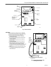
´ To avoid this time delay, press Select.
² Press Select and Enter keys simultaneously to begin
programming the load operating mode (heat or cool).
The display will indicate heat or cool and the stage
number.
¶ Press Set (down arrow) to change to cooling. Set (up
arrow) will change back to heating.
º Press Enter to program the displayed mode into
memory.
¾ Press Select to go to the next step.
µ Repeat steps 6 through 8 for additional changes.
Programming Stage Control Values
³ If you have a 0 to 18 Vdc output T775J, go to the
Calibration Procedure for 0 to 18 Vdc Output T775
before continuing to program the stage control values.
The Series 90 and 4-20 mA output T775J Controller
does not require calibration, so proceed to step 2.
IMPORTANT
When programming all stages ,it is important to note
that the first stage designated on the LCD display is
always the modulating output.
· Press Select to display the current stage setpoint.
» Press Set (up arrow) to increase or Set (down arrow) to
decrease the display to the desired setpoint.
¿ Press Enter to enter the displayed value into memory.
´ Press Select to display the current stage throttling
range or switching differential.
² Press Set (up arrow) to increase or Set (down arrow) to
decrease the display to the desired throttling range or
switching differential.
¶ Press Enter to enter the displayed value into memory.
º Repeat steps 2 through 7 to program each additional
stage.
IMPORTANT
After initial programming, altering the setpoint up or
down for stage 1 will result in a change in setpoint 2
by the same number of degrees and in the same
direction. If increasing or decreasing the setpoint for
stage 1 results in exceeding the control limits (-40
°
F
to +220
°
F) for stage 2, the control will not allow the
user to enter a value for stage 1 higher or lower than
this limit. This will allow for easy sequential output
staging to be modified while keeping the margin
intact between setpoints.
Programming Reset Values
³ Press Select to display the current reset compensation
setpoint (Sensor B).
· Press Set (up arrow) to increase or Set (down arrow) to
decrease the display to the desired setpoint.
» Press Enter to enter the displayed value into memory.
¿ Press Select to display the current Reset Ratio B
value.
´ Press Set (up arrow) to increase or Set (down arrow) to
decrease the display to the desired Reset Ratio B
value.
² Press Enter to enter the displayed value into memory.
¶ Press Select to display the current Reset Ratio A.
º Press Set (up arrow) to increase or Set (down arrow) to
decrease the display to the desired Reset Ratio A
value.
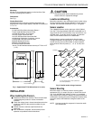
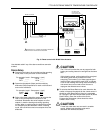
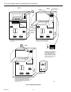
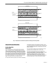
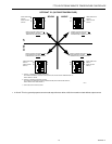
³ Set the reset direction determined previously by setting
the DIP switch in the upper right corner of the T775
(see Fig. 5). Switch 1 should be open to reset the
control point
up
and
closed
to reset the control point
down
.
· Set the reset action determined previously by setting
the DIP switch in the upper right corner of the T775J.
Switch 2 should be
open
if the reset is to occur when
the outdoor temperature is
below
the reset
compensation setpoint and
closed
if the reset is to
occur when the outdoor air temperature is
above
the
reset compensation setpoint.
» Before programming the T775J, verify that the °F/°C
selection jumper is properly installed. The T775J is
shipped from the factory with the jumper installed in the
°F position. If °C is desired, remove the jumper.
¿ Apply power to the device. The device will begin
counting down from 210. This countdown sequence will
last for approximate 3-1/2 minutes.
Stage Setpoint
Differential/
Throttling Range
Operating
Mode
Stage 1 72°F 2°F Heat
Stage 2 70°F 2°F Heat