


5
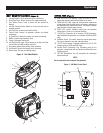
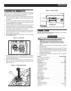
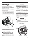
1. Carrying Handle: Lift the generator by this handle only.
2. Spark Plug Cover: Allows access to the engine spark plug.
3. Fuel System Primer: Used to prime the fuel system for
starting.
4. Fuel Cap Pressure Valve: Allows air to enter the fuel tank to
equalize pressure.
5. Fuel Tank Cap: Access to fuel tank for filling.
6. Control Panel: location of generator controls and output
receptacles.
7. Air Intake Slats: Allows for cooling air to enter the housing.
8. Muffler: Lowers engine exhaust noise.
9. Choke: Cold engine starting aid
10. Left Side Service Cover: Allows access to air filter, fuel filter
(no fuel filter on 800W models) and oil fill.
11. Vent Hoses: Hoses allow venting of the carburetor.
12. Fuel Shutoff: Controls fuel supply to the carburetor.
13. Starter Rope: Pull rope for starting engine.
Figure 2 - Unit Identification
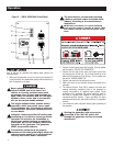
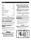
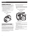
14. LOW OIL LEVEL LED (yellow): Lights up when oil level is
below safe operating level and the engine shuts down..
15. OVERLOAD LED (red): Lights up if the generator experiences
a load greater than the rated output, low voltage, overheats or
the powered circuit experiences a short. The output is stopped
even though the engine keeps running.
16. READY LED (green): Indicates output from the generator
unless there is a low oil or overload condition.
17. 12 VDC Plug: Connection for re-charging 12VDC automotive-
style batteries while generator is in operation (1600 and 2000
only).
18. EcoMode Switch: This switch slows the engine speed when
the load is reduced to save fuel and engine wear.
19. 12 VDC Circuit Breaker: Overload protection for the 12 VDC
charging system (1600 and 2000 only).
20. Ground (Earth) Connection Lug: Grounding point for the
generator; consult state and local electrical codes before use
(floating ground).
21. 120 VAC Receptacles: Two (2) receptacles for connecting
electrical devices.
NOTE:
Do not exceed the rated output of the generator.
Figure 3 - 800 Watt Control Panel
Operation