


Page 8 — English
ASSEMBLY
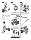
INSTALLING TRIGGER HANDLE HOLDER,
SPRAY WAND HOLDER AND HOSE STORAGE
See Figure 3 - 4.
Raise handle as described in the Raising and Lowering
Handle section.
Place hose storage onto the handle as shown.
Align the holes in the hose storage with the holes in the
handle.
Insert long screw (1/4-20 x 2.27 in.) through the holes in
the left side of the handle and hose storage.
Place nut onto long screw and tighten.
Place the trigger handle holder onto the handle as shown.
Align the holes in the trigger handle holder with the holes
in the hose storage and the handle.
Insert second long screw through the holes in handle,
hose storage, and trigger handle holder.
Slide washer onto screw. Then, place nut onto screw and
tighten.
Place spray wand holder onto pressure washer frame.
Align the holes in the spray wand holder with the holes
in the pressure washer frame.
Insert short screw (1/4-20 x 1.85 in.) through the holes in
the spray wand holder and the pressure washer frame.
Place nut onto screw and tighten.
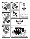
ASSEMBLING THE TRIGGER HANDLE
See Figure 5.
Place the threaded end of the spray wand in the connector
on the end of the trigger handle.
Turn the connector clockwise until it stops. This secures
the spray wand in place.
CONNECTING HIGH PRESSURE HOSE TO
TRIGGER HANDLE
See Figure 6.
Screw the collar on the high pressure hose into the trigger
handle inlet coupler by turning the hose collar clockwise.
Pull on the hose to be certain it is properly secured.
CONNECTING THE HIGH PRESSURE HOSE TO
THE PUMP
See Figure 7.
After the high pressure hose has been uncoiled and attached
to the spray wand:
Align the collar on the threaded nipple on the pump.
Insert the nozzle on the end of the high pressure hose
collar into the threaded nipple.
Turn the collar clockwise to tighten the hose securely to
the pump.
Pull on the hose to be certain it is properly secured.
PACKING LIST
Pressure Washer
25 ft. High Pressure Hose
Trigger Handle Holder
Spray Wand Holder
Phillips Screw [1/4-20 x 2.27 in.] (2)
Phillips Screw (1/4-20 x 1.85 in.)
Nuts (3)
Trigger Handle
Spray Wand
5-in-1 Change Over Nozzle
Injection Hose plus Filter
Washer
4-Cycle Engine Lubricant (SAE 30 or SAE 10W30)
High Pressure Hose Storage
Operator’s Manual
TOOLS NEEDED
See Figure 1a.
The following tools (not included or drawn to scale) are
needed for assembly:
7/16 in. combination wrench
Phillips screwdriver
WARNING:
If any parts are damaged or missing do not operate this
product until the parts are replaced. Use of this product
with damaged or missing parts could result in serious
personal injury.
WARNING:
Do not attempt to modify this product or create acces-
sories not recommended for use with this product. Any
such alteration or modification is misuse and could result
in a hazardous condition leading to possible serious
personal injury.
WARNING:
To prevent accidental starting that could cause serious
personal injury, always disconnect the engine spark plug
wire from the spark plug when assembling parts.
RAISING AND LOWERING THE HANDLE
See Figure 2.
To raise the handle: pull the handle up until the handle
release knob snaps through the locking hole to secure
the handle in place.
To lower the handle: pull the handle release knob out
then lower the handle to the position shown in figure 2.